Design and function
MIG/MAG welding
38
099-005640-EW501
04.06.2020
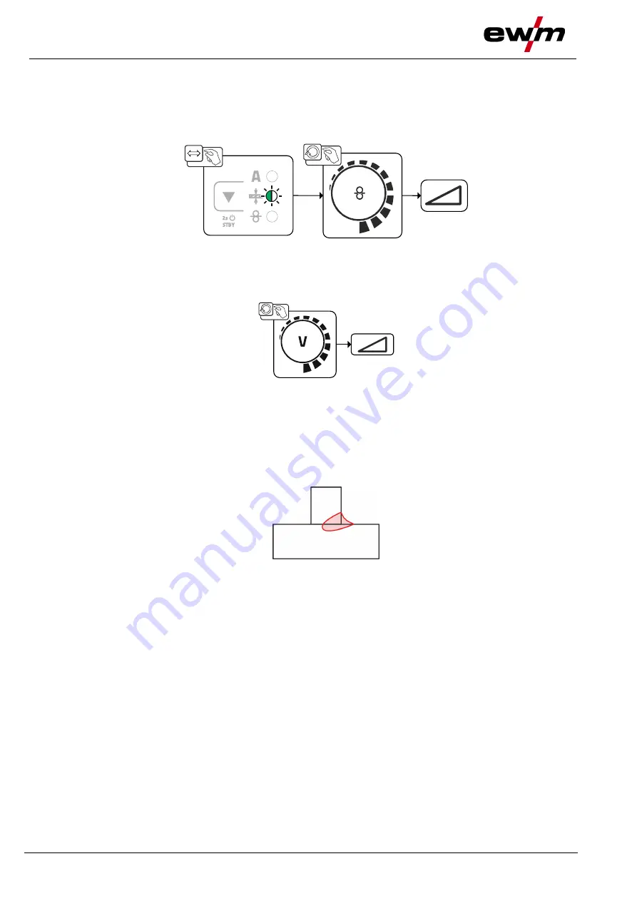
5.2.7.2 Operating point setting using material thickness
Automatic display mode switching:
If the wire speed or the voltage is changed, the display will switch briefly to show the respective
parameter. This means that you don't have to change the display mode before setting the
parameter.
Figure 5-22
5.2.7.3 Arc length
Setting range: -5 V to +5 V
Figure 5-23
The basic settings are now completed. Other welding parameters have already been set optimally in the
factory; they can, however, be modified to suit individual requirements.
5.2.8 forceArc / forceArc puls
Heat-reduced, directionally-stable and powerful arc with deep fusion penetration for the upper power ran-
ge.
Figure 5-24
• Smaller included angle due to deep penetration and directionally stable arc
• Excellent root and sidewall fusion
• Secure welding also with very long stick-outs
• Reduced undercuts
• Manual and automated applications
You can make use of these properties after selecting the forceArc process
> see 5.2.6 chapter
.
As with pulse arc welding, it is important to make sure of a good welding current connection.
• Keep welding current cables as short as possible and ensure that cable cross-sections are adequate!
• Fully unroll welding current cables, torche hose packages and, if applicable, intermediate hose packa-
ges. Avoid loops!
• Use welding torches, preferably water-cooled, that are suitable for the higher power range.
• Use welding wire with adequate copper coating when welding steel. The wire spool should have layer
spooling.
Unstable arc!
Welding current cables that are not fully unrolled can cause faults in the arc (flickering).
• Fully unroll welding current cables, torch hose packages and, if applicable, intermediate hose
packages. Avoid loops!


