Design and function
MIG/MAG welding
099-004833-EW501
22.04.2013
41
5.10.4.4 Accessory components for operating point setting
The operating point can also be set with various accessory components such as
• remote
controls
• special
torches
• PC
software
• robot and industrial bus interfaces (optional mechanised welding interface required – not possible for
all machines in this series!)
You will find an overview of accessory components in the "Accessories" chapter. See the operating
instructions for the machine in question for a more detailed description of the individual machines and
their functions.
5.10.5 MIG/MAG
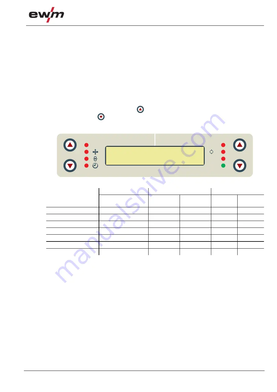
welding data display
To the left and right of the LCD display on the control there are 2 “arrow keys” on each side for selecting
the welding parameter to be displayed. The
button is used to scroll through the parameters from the
bottom upwards and the
button is used to scroll downwards from the top.
As soon as changes have been made to the settings after welding (display on hold values), the display
switches back to the nominal values.
Figure 5-9
Parameter
Before welding
During welding
After welding
Nominal value
Actual value
Nominal
value
Hold
value
Nominal
value
Welding current
Material thickness
Wire speed
Welding voltage
Motor current
JOB no.
Operating time
A
V
Job Nr
Hold
A
M
Expert
500A 49.9V


