Design and function
Remote control
099-005325-EW501
01.02.2017
33
5.5
Remote control
The remote controls are operated on the 7-pole remote control connection socket (digital).
5.6
Interfaces for automation
WARNING
Do not carry out any unauthorised repairs or modifications!
To avoid injury and equipment damage, the unit must only be repaired or modified by
specialist, skilled persons!
The warranty becomes null and void in the event of unauthorised interference.
• Appoint only skilled persons for repair work (trained service personnel)!
Unsuitable control cables or incorrect input/output signal assignment can cause damage to the
machine. Use shielded control cables only.
5.6.1
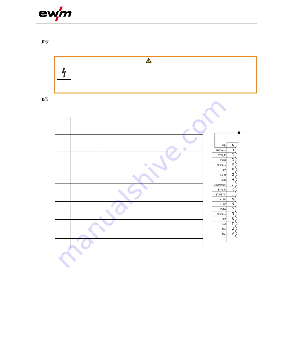
Automation interface
Pin
Input /
output
Description
Diagram
A
Output
PE
Connection for cable shielding
D
Output
(open
collector)
IGRO
Current flows signal I>0 (maximum load 20
mA / 15 V)
0 V = welding current flows
E
+
R
Input
Not/Aus Emergency stop for higher level shut-down
of the power source.
To use this function, jumper 1 must be
unplugged on PCB M320/1 in the welding
machine. Contact open
welding current
off
F
Output
0 V
Reference potential
G/P
Output
I>0
Power relay contact, galvanically isolated
(max. +/-15 V / 100 mA)
H
Output
Uist
Welding voltage, measured against pin F,
0-10 V (0 V = 0 V; 10 V = 100 V)
L
Input
Str/Stp Start = 15 V / Stop = 0 V
1)
M
Output
+15 V
Voltage supply (max. 75 mA)
N
Output
-15 V
Voltage supply (max. 25 mA)
S
Output
0 V
Reference potential
T
Output
Iist
Welding current, measured on pin F;
0-10 V (0 V = 0 A, 10 V = 1000 A)
1
) The operating mode is given by the wire feed unit (the start / stop function equates to pressing
the torch trigger and is used in mechanised applications, for example).


