background image


Design and function

Installation


099-005084-EW501 

22.09.2011


23


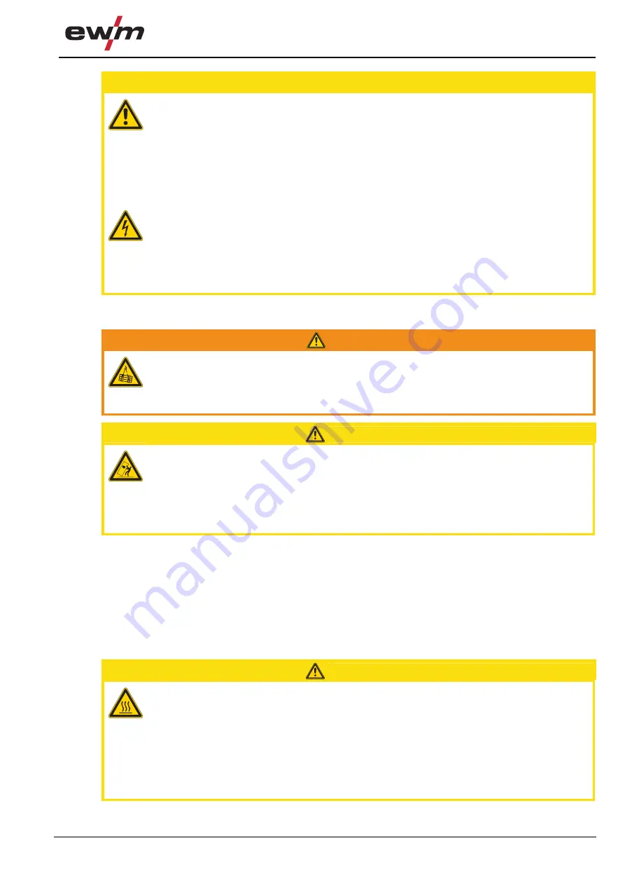
  CAUTION


Damage due to incorrect connection! 
Accessory components and the power source itself can be damaged by incorrect 
connection! 
•  Only insert and lock accessory components into the relevant connection socket when the 

machine is switched off. 

•  Comprehensive descriptions can be found in the operating instructions for the relevant 

accessory components. 

•  Accessory components are detected automatically after the power source is switched on. 


Using protective dust caps! 
Protective dust caps protect the connection sockets and therefore the machine against 
dirt and damage. 
•  The protective dust cap must be fitted if there is no accessory component being operated 

on that connection. 

•  The cap must be replaced if faulty or if lost! 


5.2


Installation


WARNING


Risk of accident due to improper transport of machines that may not be lifted! 
Do not lift or suspend the machine! The machine can fall down and cause injuries! The 
handles and brackets are suitable for transport by hand only! 
•  The machine may not be lifted by crane or suspended! 


CAUTION


Installation site! 
The machine must not be operated in the open air and must only be set up and 
operated on a suitable, stable and level base! 
•  The operator must ensure that the ground is non-slip and level, and provide sufficient 

lighting for the place of work. 

•  Safe operation of the machine must be guaranteed at all times. 


5.3


Machine cooling


To obtain an optimal duty cycle from the power components, the following precautions should be 
observed:


Ensure that the working area is adequately ventilated.


Do not obstruct the air inlets and outlets of the machine.


Do not allow metal parts, dust or other objects to get into the machine.


5.4


Workpiece lead, general 


CAUTION


Risk of burns due to incorrect connection of the workpiece lead! 
Paint, rust and dirt on the connection restrict the power flow and may lead to stray 
welding currents. 
Stray welding currents may cause fires and injuries! 
•  Clean the connections! 
•  Fix the workpiece lead securely! 
•  Do not use structural parts of the workpiece as a return lead for the welding current! 
•  Take care to ensure faultless power connections! 


Summary of Contents for MIRA 151

Page 1: ...ng machine GB Mira 151 KGE Mira 221 MV KGE Mira 251 KGE Mira 301 KGE M1 02 099 005084 EW501 22 09 2011 Register now For your benefit Jetzt Registrieren und Profitieren www ewm group com Details for ew...

Page 2: ...ther form of liability regardless of type shall be accepted This exclusion of liability shall be deemed accepted by the user on commissioning the equipment The manufacturer is unable to monitor whethe...

Page 3: ...w 17 4 3 Machine control Operating elements 18 4 3 1 Mira 151 18 4 3 2 Mira 221 MV 19 4 3 3 Mira 251 20 4 3 4 Mira 301 21 5 Design and function 22 5 1 General 22 5 2 Installation 23 5 3 Machine coolin...

Page 4: ...nufacturer s declaration to the end user 43 6 5 Meeting the requirements of RoHS 43 7 Rectifying faults 44 7 1 Customer checklist 44 8 Technical data 45 8 1 Mira 151 221 MV 251 301 45 9 Accessories 46...

Page 5: ...l in the page margin CAUTION Working or operating procedures which must be closely observed to prevent possible minor personal injury The safety information includes the CAUTION keyword in its heading...

Page 6: ...scription Press Do not press Turn Switch 0 1 Switch off machine 0 1 Switch on machine ENTER enter the menu NAVIGATION Navigating in the menu EXIT Exit the menu Time display example wait 4s press Inter...

Page 7: ...s and burns on contact Even low voltages can cause you to get a shock and lead to accidents Do not touch any live parts in or on the machine Connection cables and leads must be free of faults Switchin...

Page 8: ...ith flammable material Connect welding leads correctly Risk of accidents if these safety instructions are not observed Non observance of these safety instructions is potentially fatal Carefully read t...

Page 9: ...suspend all conductive power source components like casing transport vehicle and crane frames so they are insulated Do not place any other electronic devices such as drillers or angle grinders etc on...

Page 10: ...he user is responsible for any interference caused by welding In order to evaluate any possible problems with electromagnetic compatibility in the surrounding area the user must consider the following...

Page 11: ...d by crane or suspended CAUTION Risk of tipping There is a risk of the machine tipping over and injuring persons or being damaged itself during movement and set up Tilt resistance is guaranteed up to...

Page 12: ...s of dust acid corrosive gases or substances may damage the equipment Avoid high volumes of smoke vapour oil vapour and grinding dust Avoid ambient air containing salt sea air Non permissible ambient...

Page 13: ...line with proper usage and by trained or expert staff Do not modify or convert the equipment improperly 3 1 Applications 3 1 1 MIG MAG standard welding Metal arc welding using a wire electrode whereb...

Page 14: ...ted conversion work not specifically authorised by the manufacturer The original copy of the declaration of conformity is enclosed with the unit 3 3 3 Welding in environments with increased electrical...

Page 15: ...overview 4 1 Front view Figure 4 1 Item Symbol Description 0 1 Carrying handle 2 Machine control See Machine control operating elements chapter 3 Wheels guide castors 4 Connection socket workpiece lea...

Page 16: ...iption 0 1 Securing elements for shielding gas cylinder strap chain 2 Key button Automatic cutout Wire feed motor supply voltage fuse press to reset a triggered fuse 3 Connecting nipple G shielding ga...

Page 17: ...84 EW501 22 09 2011 17 4 2 1 Inside view Figure 4 3 Item Symbol Description 0 1 Inspection window for checking the wire and handle for opening the cover 2 Wire delivery unit cover 3 Wire feed unit 4 W...

Page 18: ...in switch machine on off 4 Rotary dial Spot and interval times Infinite adjustment of the welding time 0 20s in Spots and interval operating mode 5 Rotary dial Pause time Infinite adjustment of the pa...

Page 19: ...chine switched off 3 0 40 0V 230 V 400V position Machine switched on with 2 x 400V mains connection 4 Rotary dial Spot and interval times Infinite adjustment of the welding time 0 20s in Spots and int...

Page 20: ...e on off 4 Rotary dial Spot and interval times Infinite adjustment of the welding time 0 20s in Spots and interval operating mode 5 Rotary dial Pause time Infinite adjustment of the pause time 0 20s i...

Page 21: ...4 Rotary dial Spot and interval times Infinite adjustment of the welding time 0 20s in Spots and interval operating mode 5 Rotary dial Pause time Infinite adjustment of the pause time 0 20s in Interva...

Page 22: ...feed units are equipped with moving parts which can trap hands hair clothing or tools and thus injure persons Do not reach into rotating or moving parts or drive components Keep casing covers closed d...

Page 23: ...and brackets are suitable for transport by hand only The machine may not be lifted by crane or suspended CAUTION Installation site The machine must not be operated in the open air and must only be set...

Page 24: ...g instructions The resulting network has to be suitable for operating devices according to protection class 1 CAUTION Operating voltage mains voltage The operating voltage shown on the rating plate mu...

Page 25: ...r TT networks with a neutral conductor and a protective conductor L1 N PE Figure 5 2 Legend Item Designation Colour code L1 Outer conductor brown N Neutral conductor blue PE Protective conductor green...

Page 26: ...ure 5 3 Legend Item Designation Colour code L1 Outer conductor 1 black L2 Outer conductor 2 brown L3 Outer conductor 3 PE Protective conductor green yellow Insert mains plug of the switched off machin...

Page 27: ...o TN TT or IT networks with a protective conductor as available L1 L3 L2 PE Figure 5 4 Legend Item Designation Colour code L1 Outer conductor 1 black L2 Outer conductor 2 brown L3 Outer conductor 3 gr...

Page 28: ...with plastic core use with guide tube Welding torch with spiral guide use with capillary tube Preparation work for connecting welding torches with a plastic core Push forward the capillary tube on th...

Page 29: ...d welding current shielding gas and torch trigger 2 Welding torch hose package 3 Welding torch 4 Connection socket workpiece lead 5 Workpiece lead 6 Workpiece Insert the central plug for the welding t...

Page 30: ...ions from the gas manufacturer and in any relevant regulations concerning the use of compressed air Place shielding gas cylinders in the holders provided for them and secure with fixing devices Avoid...

Page 31: ...iption 0 1 Securing elements for shielding gas cylinder strap chain 2 Bracket for shielding gas cylinder 3 Connecting nipple G shielding gas connection Place the shielding gas cylinder into the releva...

Page 32: ...lding gas quantity MAG welding Wire diameter x 11 5 l min MIG brazing Wire diameter x 11 5 l min MIG welding aluminium Wire diameter x 13 5 l min 100 argon TIG Gas nozzle diameter in mm corresponds to...

Page 33: ...ed nut For fixing the wire spool Loosen knurled nut from spool holder Fix welding wire reel onto the spool holder so that the carrier pin locks into the spool bore Fasten wire spool using knurled nut...

Page 34: ...e if necessary use V groove rollers with for steel wires and other hard wires use U groove rollers for aluminium wires and other soft alloyed wires Figure 5 9 Item Symbol Description 0 1 Pressure unit...

Page 35: ...thus injure persons Do not reach into rotating or moving parts or drive components Keep casing covers closed during operation Risk of injury due to welding wire escaping in an unpredictable manner Wel...

Page 36: ...ve on the drive roller into the capillary tube or plastic core with support tube Push the clamping units downwards and fold the pressure unit back up The wire electrode must be located in the groove o...

Page 37: ...Symbol Description 0 1 Allen screw Securing the wire spool retainer and adjustment of the spool brake Tighten the Allen screw 8 mm in the clockwise direction to increase the braking effect NOTE Tighte...

Page 38: ...ng NOTE It is not necessary to set other parameters The permanently set gas pre flow time is 200ms The wire burn back time is automatically controlled by the machine control using the welding characte...

Page 39: ...workpiece Welding current flows 2nd cycle Release torch trigger wire feed motor stops arc is extinguished 5 10 3 Latched operation t t t I 1 2 3 4 Figure 5 14 1st cycle Press and hold torch trigger S...

Page 40: ...elding t t1 I t t Figure 5 15 Start Press and hold torch trigger Shielding gas is expelled gas pre flows Arc ignites after the wire electrode makes contact with the workpiece Welding current flows The...

Page 41: ...d gas pre flows Arc ignites after the wire electrode makes contact with the workpiece Welding current flows The wire feed stops after the pulse time expires Arc is extinguished The process is repeated...

Page 42: ...d valve Gas cylinder securing elements Operating message safety and adjustment devices Functional test Other general condition 6 2 2 Monthly maintenance tasks Casing damage front rear and side walls W...

Page 43: ...pean provisions guideline 2002 96 EG of the European Parliament and the Council of January 27th 2003 used electric and electronic equipment may no longer be placed in unsorted municipal waste It must...

Page 44: ...nching wire electrodes chapter Check settings and correct if necessary a Worn wire rolls Check and replace if necessary a Wire feed motor without supply voltage automatic cutout triggered by overloadi...

Page 45: ...V Mains connection lead H07RN F4G2 5 H07RN F5G2 5 H07RN F4G2 5 Mains voltage tolerance 15 1 x 230 V 1 x 230 V or 2 x 400 V 3 x 400 V 3 x 400 V Frequency 50 60Hz Mains fuse safety fuse slow blow 1 x 1...

Page 46: ...ies Type Designation Item no ADAP DZA EZA Adapter for welding torches with Dinse connector to Euro central connector on the machine 094 016765 00000 AK300 Adapter for K300 basket coil 094 001803 00001...

Page 47: ...ocket when the machine is switched off 10 1 Wire feed rollers 10 1 1 2 roll drive 10 1 1 1 Wire feed roller for steel wires Type Designation Item no FE 1DR2R 0 6 0 8 Drive rollers 37mm 2 rollers steel...

Page 48: ...8 1 0 Drive rollers 37 mm steel 092 000840 00000 FE 2DR4R 0 9 1 2 Drive rollers 37 mm steel 092 000841 00000 FE 2DR4R 1 0 1 2 Drive rollers 37 mm steel 092 000842 00000 10 1 2 2 Wire feed rollers for...

Page 49: ...Appendix A Overview of EWM branches 099 005084 EW501 22 09 2011 49 11 Appendix A 11 1 Overview of EWM branches...

Reviews: