Commissioning
Field bus connection and configuration
18
Item No.: 099-008225-EWM01
4.4.3.4 Connection of the CAN DeviceNet module
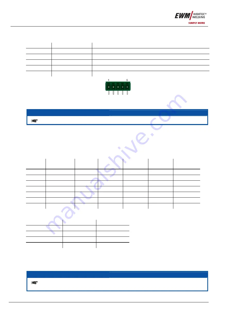
The field bus is connected via a 5-pole panel connector as follows:
Pin Signal
Function
1
V-
Supply voltage reference mass
2
CAN_L
Low signal cable of the CAN difference signal
3
CAN_SHLD
Connection for cable shield
4
CAN_H
High signal cable of the CAN difference signal
5 V+
+24V
power
supply
Figure 4-9
NOTE
The 24V power supply is essential for operating the field bus!
4.4.3.5 Network settings
In the DeviceNet, every subscriber must be assigned a unique and one-off address in the range of 0 to
63. Every subscriber must also be set to the same baud rate.
Eight configuration switches are used to set the baud rate and address.
Address (MAC)
The address is set as follows via switches 3 to 8:
MAC ID
Switch 3
(MSB)
Switch 4
Switch 5
Switch 6
Switch 7
Switch 8
(LSB)
0
Off
Off
Off Off Off Off
1
Off
Off
Off Off Off On
2 Off
Off Off Off On Off
3 Off
Off Off Off On On
... ...
... ...
...
...
...
62
On
On
On On On Off
63
On
On
On On On On
Baud rate
The baud rate is set via configuration switches 1 and 2:
Baud rate
Switch 1
Switch 2
125k Off Off
250k Off On
500k On Off
Reserved On
On
4.4.3.6 EDS configuration file
The module settings can be modified via an EDS file. In this case, however, the option of configuration via
the bus master is a requirement.
NOTE
For the remaining steps in the setup process, please refer to the "Special field bus
features when setting up the field bus modules" chapter.


