background image


Installation Manual MK-Series       


8/10


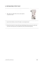
2.2 INSTALLATION OF THE PT UNIT 
 

1.


Place the PT on a flat surface in the correct position 
to mount the bolts. 


2.


Fasten the M12 bolts and check if the bolts are securely fastened. 

3.


Remove the connector (be carefull that you don’t damage the wire). Fasten the M12 bolts 
and check if the bolts are securely fastened. Put the connector back in place. 


Summary of Contents for MK 2000HD

Page 1: ...Vlierberg 4 06A 3755 BS Eemnes The Netherlands Phone 31 0 85 0441855 NL E mail info evvelongrange com Web www evvelongrange com MK Series ...

Page 2: ...LATED DOCUMENTS 3 FFC COMPLIANCE 2 SUPPORT SERVICES 2 RETURNS 2 SHIPMENT 3 SAFETY INSTRUCTIONS 3 1 INTRODUCTION EQUIPMENT SUPPLIED 5 2 INSTALLATION 6 2 1 INSTALLATION OF THE POWER BOX 6 2 2 INSTALLATION OF THE PT UNIT 8 2 3 CONNECTION OF THE CAMERA TO THE PT UNIT 9 EVVE LONG RANGETM ...

Page 3: ...eTM products 2000HD Series High Definition Camera System The information in this manual is subject to change without notice Please refer to our website for the latest information NOTE All graphics contained within this document including screenshots and other displays are for reference use only and are subject to change Copyright 2020 by Evve Long Range B V ELR ELR has intellectual property rights...

Page 4: ...ioning System Please contact ELR for technical assistance support evvelongrange com 31 0 85 0441855 NL This item was thoroughly tested and carefully packed at the factory prior to shipping Upon acceptance by the carrier the carrier assumes responsibility for the item s safe arrival If you receive the item in a damaged condition apparent or concealed a claim for damage must be made to the carrier I...

Page 5: ...tructions If the unit is defective please contact the Customer Service Department for technical assistance Liability It is the sole responsibility of the installer to provide proper installation in compliance with all local codes and regulations WARNING Do not remove covers There are no user serviceable parts inside CAUTION Mount the camera system before the power is applied After the power is app...

Page 6: ...n or woman CLASS 3 EYE SPECULAR REFLECTION HAZARD Never aim the laser at a person s eye or stare at the laser from within the beam Keep the beam path above or below eye level for one seated or standing Laser safety eyewear is needed if MPE Maximum Permissible Exposure is exceeded Don t view beam directly with optical instruments unless a protective filter is used Only experienced and authorized in...

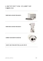
Page 7: ...Installation Manual MK Series 5 10 POWER BOX CONNECTION CABLES POWER BOX CONNECTION CABLES CAMERA HOUSING WITH SUNSHIELD 12 BOLTS M12 STAINLESS STEEL ALLEN KEY SET ...

Page 8: ... the red camera power cable 2 1 Place the camera cable through the cable gland NOTE Before starting installation Choose a flat surface or bracket Have the bolts available Do NOT power the systems until all devices are connected CAUTION The bolts that are used to install the camera must be securely fastened After installation and before turning on the camera check if the camera moves freely and has...

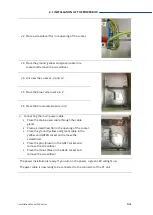
Page 9: ... the main power cable through the cable gland Place a screwdriver flat in the opening of the socket Place the ground yellow and green cable in the yellow and GREEN socket and remove the screwdriver Place the plus brown in the GREY socket and remove the screwdriver Place the minus blue in the BLUE socket and remove the screwdriver The power installation is ready If you turn on the power a green LED...

Page 10: ... flat surface in the correct position to mount the bolts 2 Fasten the M12 bolts and check if the bolts are securely fastened 3 Remove the connector be carefull that you don t damage the wire Fasten the M12 bolts and check if the bolts are securely fastened Put the connector back in place ...

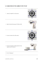
Page 11: ...ECTION OF THE CAMERA TO THE PT UNIT 1 Remove the bolts from the tilt axle 2 Slide the camera housing on the drive shaft 3 Secure the bolts on the drive shaft 4 Connect the power and data cable from the power box to the camera 5 Turn on the power ...

Page 12: ...Installation Manual MK Series 10 10 Vlierberg 4 06A 3755 BS Eemnes The Netherlands Phone 31 0 85 0441855 NL E mail info evvelongrange com Web www evvelongrange com ...

Reviews: