background image


Installation Manual MK-Series       


14/24


ADJUSTING SERIAL PARAMETERS 


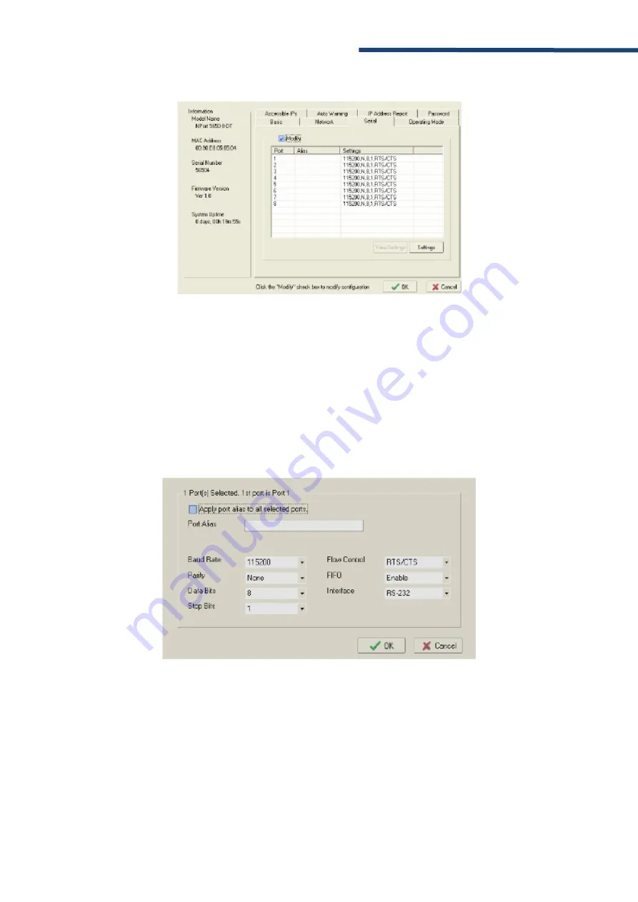
The  serial  communication  parameters  for  each  device  port  can  be  configured  through  NPort 
Administrator. Open your device server’s configuration window, using the same method you used 
to configure network parameters. On the Serial screen, select the Modify check box and then 
select the device port that you wish to configure. Click Settings to configure the selected device 
port. 
 
Modify the parameters as needed. When you are ready to restart the device server with the new 
settings, click OK


3. PASSTRHOUGH PORT MOXA 

Summary of Contents for MK 2000HD

Page 1: ...Vlierberg 4 06A 3755 BS Eemnes The Netherlands Phone 31 0 85 0441855 NL E mail info evvelongrange com Web www evvelongrange com MK Series ...

Page 2: ... CHARM 8 2 7 NTP SERVER ADDRESS 9 3 PASSTRHOUGH PORT MOXA 10 3 1 INSTALLING NPORT ADMINISTRATOR 10 3 2 SEARCHING FOR DEVICE SERVERS OVER A LAN 10 3 3 ADJUSTING GENERAL SETTINGS 11 3 4 CONFIGURING SERIAL COMMUNICATION PARAMETERS 13 3 5 MAPPING COM PORT TO DEVICE 15 3 6 CONFIGURATION BY WEB CONSOLE 18 4 OPERATING THE CAMERA WITH KEY BOARD KBD300A 19 4 1 USE THE DIFFERENT SPEEDS 19 4 2 SET OR CHANGE ...

Page 3: ...ng Evve Long RangeTM products 2000HD High Definition Camera System The information in this manual is subject to change without notice Please refer to our website for the latest information NOTE All graphics contained within this document including screenshots and other displays are for reference use only and are subject to change Copyright 2020 by Evve Long Range B V ELR ELR has intellectual prope...

Page 4: ...rference to radio communications Operation of this equipment in a residential area is likely to cause harmful interference in which case the user will be required to correct the interference at his own expense This device complies with Part 15 of the FCC Rules Operation is subject to the following two conditions 1 this device may not cause harmful interference and 2 this device must accept any int...

Page 5: ...le of supporting at least four times the combined weight of the pan tilt unit mounted payloads and cabling 7 For outdoor use use only corrosion resistant hardware to fasten the mount and payloads e g stainless steel screws 8 The unit should not be installed in environments that present conditions beyond the environmental specification of pan tilt unit Installation near heat sources such as radiato...

Page 6: ...andards for temperature shock and vibration specifications For environmental protection the camera systems use an IP67 camera head enclosure and IP66 positioner enclosure For more information on specifications and datasheets please refer to specific product pages at Evve Long Range website www evvelongrange com downloads At 50km the pixels per meter in height will be 8 Assuming man is 2m approx th...

Page 7: ...and the password vision4ce 2 2 OPERATING IN MULTICAST Looking at the start screen towards the middle you can see the option to Edit the template xml file Click the Edit button and then follow the instructions in the file to Copy to another file Edit the copied file to o Remove the lower case x from the xStreamRTSPCfg0 entry o Change the bUseUnicast true to bUseUnicast false Save the file Ensure th...

Page 8: ...are update over serial connection are not covered here PRE REQUISITES You will need a computer with Ethernet connection to the CHARM an update file and a web browser You will need to know the IP address of the CHARM the default is 10 0 0 2 PERFORMING AN UPDATE Choose Update CHARM from the CHARM Main Page then click on the Choose file button and navigate to the update file Once it has finished uplo...

Page 9: ...ould be 255 0 0 0 and for IP addresses in the 192 168 1 x range the subnet mask should be 255 255 255 0 You can optionally add a gateway address if you need the CHARM to connect to the internet to get internet NTP time for instance Upon pressing the submit Set IP button the IP address will be changed and the CHARM rebooted To view the CHARM Web Updater again you will need to log in again at the ne...

Page 10: ...can select which one is loaded by the CHARM software Select the required configuration file and press the submit Set config button If the CHARM has secondary user config files you can also select these The selected files will be used next time the CHARM is rebooted There is a reboot button on the home page 2 VIDEOSTREAMS THROUGH CHARM 10CE ...

Page 11: ... you can set up an NTP server Enter the server address and press Set Address After the CHARM boots it can take around 3 minutes for the time to synchronise If you wish to use an NTP server on the internet you will need to set the gateway address in the IP address page 2 VIDEOSTREAMS THROUGH CHARM 10CE ...

Page 12: ...allation is complete 3 2 SEARCHING FOR DEVICE SERVERS OVER A LAN The Broadcast Search function is used to locate all NPort 5400 device servers that are connected to the same LAN as your computer Since the Broadcast Search function searches by MAC address and not IP address all NPorts connected to the LAN will be located regardless of whether or not they are part of the same subnet as the host In N...

Page 13: ...in is Username admin Password moxa 3 3 ADJUSTING GENERAL SETTINGS Right click your unit in the Configuration screen and select Configure in the pop up menu If your device server is password protected the default password is moxa first select Unlock in the pop up menu and then click the Network tab in the configuration window Select the Modify checkbox for items you would like to modify The device ...

Page 14: ...ce server s configuration window using the same method you used to adjust the network parameters On the Operating Mode screen select the Modify check box and then select the device port that you wish to configure Click Settings to configure the selected device port Set the operating mode and associated parameters as needed Refer to https www moxa com Moxa media PDIM S100000213 moxa nport ia5000 se...

Page 15: ...n rate to and from the attached serial device Need to 9600 Data bits 5 6 7 8 8 The size of each data character 8 Stop bits 1 1 5 2 1 The size of the stop character 1 Parity None Even Odd Space Mark None The parity that will be used Even and Odd parity provide rudimentary error checking Space and Mark parity are rarely used None Flow control None RTS CTS DTR DSR Xon Xoff RTS CTS The method used to ...

Page 16: ...erver s configuration window using the same method you used to configure network parameters On the Serial screen select the Modify check box and then select the device port that you wish to configure Click Settings to configure the selected device port Modify the parameters as needed When you are ready to restart the device server with the new settings click OK 3 PASSTRHOUGH PORT MOXA ...

Page 17: ...llowing instructions are for device ports operating in Real COM mode For device ports operating in RFC2217 mode follow the instructions for your particular driver Real COM mode also supports TTY port mapping on Linux and UNIX systems SPECIFYING THE TARGET DEVICE SERVER In NPort Administrator click COM Mapping in the Function panel to open the COM Mapping window Right click on an empty line in the ...

Page 18: ...s screen select the COM port number that will be mapped to the device port You can map multiple COM ports at the same time by selecting the Auto Enumerating check box to number the COM ports automatically On the Serial Parameters screen adjust the settings to match your device These settings which are only used for serial printers must also match the settings on the device port Click OK when you a...

Page 19: ...sh When enabled the driver flushes only the local buffer on the host for a Win32 PurgeComm function call When disabled both the local and remote buffers are flushed If your application uses PurgeComm and it performance seems sluggish try enabling Fast Flush Always Accept Open Requests Even if the driver cannot establish a connection with the NPort the user s software will still be able to open the...

Page 20: ...enabled To enable your browser for cookies right click on your desktop s Internet Explorer icon select Properties click on the Security tab and then select the three Enable options as shown in the figure below 2 Type 192 168 127 254 in the Address input box use the correct IP address if different from the default and then press Enter 3 You will be prompted to enter the password to access the NPort...

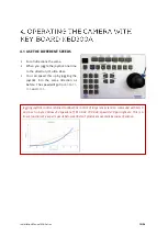
Page 21: ...this up by joggling the joystick into the same direction as before The speed will go from to and Joggling joystick control retained to allow fine control of large lens extension command with bits 5 and 6 set in byte 3 allow 254 speeds ie ff 01 60 02 70 00 d3 speed 0x70 pan right etc This is a linear function We expect speeds below 0x06 don t produce movement because of stiction ...

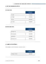
Page 22: ...position for absolute control SET END STOPS COMMAND Set Left 91 PRESET Set Right 92 PRESET Set Up 93 PRESET Set Down 94 PRESET REMOVE END STOPS COMMAND Release Left 95 PRESET Release Right 96 PRESET Release Up 97 PRESET Release Down 98 PRESET COMMAND Absolute Control 99 PRESET 4 OPERATING THE CAMERA WITH KEYBOARD ...

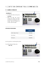
Page 23: ...ra settings press 5 AUX OFF OPERATING COMMANDS COMMAND Enter camera menu 88 PRESET Save menu 89 PRESET Exit menu 90 PRESET STARTING UP To enter the camera menu press 5 AUX ON When you enter the camera settings the camera movement will be blocked Getting out of the camera menu will unblock the camera movement again ...

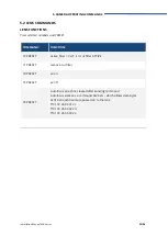
Page 24: ... 0xcf ir cut filter ACTIVE 71 PRESET remove cut filter 74 PRESET x2 on 75 PRESET x2 off 76 PRESET Autofocus one shot cleared after sending command Autofocus works as a command 0x2b etc which allows data bytes 0x01 0x02 0x03 and are passed on to the lens ff 01 00 2b 00 01 2c ff 01 00 2b 00 02 2d ff 01 00 2b 00 03 2e 5 CAMERA OPERATING COMMANDS ...

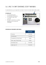
Page 25: ...laser press 6 AUX ON laser initialization To activate the laser press 3 AUX ON The laser is on but there is no active laser beam yet see operating commands OPERATING COMMANDS LASER BEAM COMMAND Start laser 6 AUX ON Activate power 3 AUX ON Less power by 10 each step OPEN Power up by 10 each step CLOSE Deactivate power 3 AUX OFF Switch laser off 6 AUX OFF ...

Page 26: ... shows state of Aux 6 o ie 0x40 means Aux 6 active o bit 5 alarm 6 is the state of the laser controller 0x20 is laser on 0x60 would be laser on and aux 6 active o 0x40 Aux 6 active o 0x20 laser active o 0x00 neither active Note the Rx knows the percentage power applied 0 100 percent shown on the OSD the percentage power is not at present supplied in the general response byte It is possible to have...

Page 27: ...Installation Manual MK Series 25 24 Vlierberg 4 06A 3755 BS Eemnes The Netherlands Phone 31 0 85 0441855 NL E mail info evvelongrange com Web www evvelongrange com ...

Reviews: