

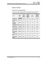


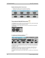


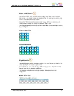


The
Multiviewer
connectors allow a monitor to be connected directly to the server, and to
display PGM and REC channels as configured in the Multicam Configuration window, in
the Monitoring tab, Multiviewer page. See the Multicam Configuration manual for a
description of the configuration parameters.
The
RS232
connector allows a tablet to be connected to the server.
The
Multiviewer
connector provides an analog Multiviewer output on a DA-15
connectors, that can be configured in CVBS, RGB HD or YUV HD.
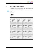
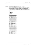
The
GPI
connector allows GPI (General Purpose Interface) devices to send or receive
electric pulses that will trigger commands on the server or to be connected with third-party
devices.
Two
PC LAN
connectors allow connection of the PC LAN interface of the EVS server to
an Ethernet network.
The
Console
connectors allow a monitor and a keyboard to be connected to the server.
The
RS422 ports
allow the server to be remotely controlled through remote panels or
third-party control devices. When a remote panel is used, it should be connected on the
first RS422 port.
Gigabit Ethernet Connectors Module
The Gigabit Ethernet Connector module of the 10GbE board is located at the bottom
center of the rear panel (5a). It is an optional module.
On Multicam version 12.05, this area can have one of the following layouts:
•
It is covered with a filler if no 10GbE is available. This is the default configuration:
•
It hosts a PCIe connector that allows the connection of the EVS server with the
XTAccess Gateway PC providing the external 10 GbE connection:
HARDWARE TECHNICAL REFERENCE MANUAL XT3 Server 12.05
5. Hardware Installation and Cabling
51
Summary of Contents for XT-3
Page 1: ...HARDWARE TECHNICAL REFERENCE MANUAL Version 12 05 November 2014 ...
Page 2: ......
Page 4: ......
Page 8: ......
Page 10: ......
Page 101: ...HARDWARE TECHNICAL REFERENCE MANUAL XT3 Server 12 05 6 Boards Description 91 ...
Page 122: ...Illustration 112 6 Boards Description EVS Broadcast Equipment SA Issue 12 05 C November 2014 ...
Page 125: ......