Assembly and Maintenance
PPC-1561
- 19 -
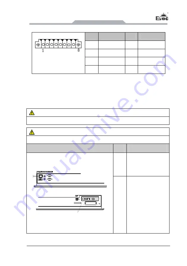
5.3.7 GPIO Port
Pin
Signal Name
Pin
Signal Name
1 GPIO1 2 GPIO2
3 GPIO3 4 GPIO4
5 GPIO5 6 GPIO6
GPIO1
(pitch: 3.81mm)
7 GPIO7 8 GPIO8
Note: By the factory default, pin 1, 2, 3 and 4 are for input while pin 5, 6, 7 and 8 are
for output. The factory default state is high level and the voltage range for
input/output signal is 0-5V.
5.4 Operation Control
Warning
The On/Off button signal will not disconnect PC power supply!
Caution
When the PC executes hardware reset, data may be lost.
Control Button
Item
Description
①
The On/Off switch
button used to power
on the PC.
②
Reset button
A pointed object or a
clip can be used to
press reset button, and
the signal will trigger
hardware reset. Then
the PC will be rebooted
(cold boot).


