


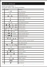


REMOTE CONTROLLER
S ignal
receptor
10
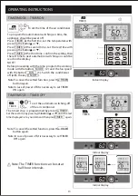
DRY
FAN
HEAT
TIMER
HEALTHY
AIR
SWING
FAN
SPEED
COOL
FEEL
DRY
FAN
HEAT
TIMER
HEALTHY
AIR
SWING
FAN
SPEED
COOL
FEEL
+
+
+
DIS
PL
AY
HE
AL
TH
Y
3D
ON
/O
FF
SW
IN
G
FA
N
TIM
ER
SU
PE
R
SL
EE
P
M
OD
E
EC
O
CL
O
C
K
R emote controller holder
DISP
LAY
HEA
LTH
Y
3D
ON/O
FF
SW
ING
FAN
TIM
ER
SUP
ER
SLE
E
P
MO
DE
ECO
CLO
CK
DISP
LAY
HEA
LTH
Y
3D
ON/O
FF
SW
ING
FAN
TIM
ER
SUP
ER
SLE
E
P
MO
DE
ECO
CLO
CK
Replacement of Batteries
Remove the battery cover plate from the rear of the remote controller,
by sliding it in the direction of the arrow.
Install the batteries according the direction (+and -)shown on the Remote
Controller.
Reinstall the battery cover by sliding it into place.
Use 2 LRO 3 AAA (1.5V) batteries . Do not use rechar geable
batteries . Replace the old batteries with new ones of the same
type when the display is no longer legible.
Do not dispose batteries as unsorted municipal waste. Collection
of such waste separately for special treatment is necessary.
NOTE:if you adjust the remote controller in cooling mode,
it will not be possible to activate the heating function in units with
heating pump . you need to take out the batteries and repeat the
procedure described above.
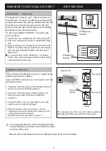
1. Direct the remote controller toward the Air conditioner.
2. Check that there are no objects between the remote control
and the Signal receptor in the indoor unit.
3. Never leave the remote controller exposed to the rays of the sun.
4. Keep the remote controller at a distance of at least 1m from the
television or other electrical appliances.
Recommendations for locating and using the remote controller holder (if present)
The remote controller be kept in a wall-mounted holder
Refer to picture 2:
When you insert the batteries for the first time in the remote
controller or if you change them, you need to program the remote
controller of only cooling or cooling and heating.
When you insert the batteries, the symbols ( ) and
( ) start fashing. If you push whatever button when
the symbol ( ) is displayed, the remote controller is
adjusted in only cooling mode . If you push whatever button when
the symbol ( ) is displayed , the remote controller is
adjusted in Cooling and heating mode.
COOL
HEAT
COOL
HEAT
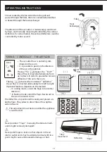
Refer to picture 1:
i.
When you open the battery cover, you can see a DIP switch on
the cover back.l
Ii. NOTE:After adjusting the function, you need to take
out the batteries and repeat the procedure described above.
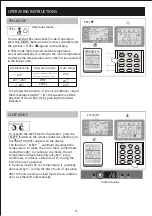
DIP switch on position
Function
The remote controller is adjusted in degree celsius
The remote controller is adjusted in only cooling mode
The remote controller is adjusted in cooling and heating mode
The remote controller is adjusted in degree fahrenheit.
Cool
Heat
C
F


