background image


 Air Conditioner Service Manual

7).An efficient earth connection must be ensured. 

8).If the power cable is damaged, it must be 

replaced by an authorized Service Centre. 

9

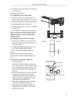
.2.4   Refrigerant piping connection


The piping can be run in the 3 directions indicated 
by numbers in the picture. When the piping is run 
in direction 1 or 3, cut a notch along the groove on 
the side of the indoor unit with a cutter. 

Run the piping in the direction of the wall hole and 
bind the copper pipes, the drain pipe and the 
power cables together with the tape with the drain 
pipe at the bottom, so that water can flow freely. 

9

.2.5 Connecting the pipes.


z

  Do not remove the cap from the pipe until 

connecting it, to avoid dampness or dirt 
from  entering. 

z

   If the pipe is bent or pulled too often, it will 

become stiff. Do not bend the pipe more 
than  three times at one point. 

z

   When extending the rolled pipe, straighten 

the  pipe by unwinding it gently as shown in 
the  picture. 

9

.2.6 Connections to the indoor unit


1).Remove the indoor unit pipe cap (check that 

there is no debris inside). 

2).Insert the fare nut and create a flange at the 

extreme end of the connection pipe. 

3).Tighten the connections by using two wrenches 

working in opposite directions. 

9

.2.7 Indoor unit condensed water drainage 

The indoor unit condensed water drainage is 
fundamental for the success of the installation. 
1).Place the drain hose below the piping, taking 

care not to create siphons. 

2).The drain hose must slant downwards to aid 

drainage. 

3).Do not bend the drain hose or leave it protruding 

or twisted and do not put the end of it in water. If 
an extension is connected to the drain hose, 
ensure that it is lagged when it passes into the 
indoor unit. 


3

2

1

Shape the connection pipe

NO

YES

Extending the  rolled pipe

torque wrench

YES

NO

NO

37

Summary of Contents for MGTC0913C-20

Page 1: ...details 5 Wiring diagram 6 Explosion view and parts 7 Precaution 8 Names of parts 9 Installation manual 10 Trouble shooting MGTC0913E 20 MGTC0913C 20 MGTC0923E 20 MGTC0923C 20 MGTC1213E 20 MGTC1213C...

Page 2: ...for the interpretation of this information nor can it assume any liability in connection with its use The information specifications and parameter are subject to change due to technical modification...

Page 3: ...GTC0923C 20 811 203 292 787 498 290 415 291 225 48 5 52 MGTC1213E 20 MGTC1213C 20 811 203 292 810 549 305 433 8 305 278 48 55 MGTC1223E 20 MGTC1223C 20 811 203 292 787 498 290 415 291 225 48 5 52 MGTC...

Page 4: ...Compressor Accumulator Heat exchange condenser Heat exchange Evaporator 2 way valve Liquid side 3 way valve Gas side Cooling Heating Gas side 3 way valve Liquid side 2 way valve Heat exchange Evaporat...

Page 5: ...button TEMP UP button TIMER button SLEEP button TEMP DOWN button To select the mode of operation In cooling mode press this button the temperature will increase 2 on the base of setting temperature In...

Page 6: ...or load of compressor is abnormity the air conditioner will shut down and show error code 7 IPM module protection IPM module has high temperature over current protection itself if there is signal feed...

Page 7: ...ling mode the set temperature ST is RT 2 After that t he system will operate in cooling mode with lowest fan speed for 30 minutes and then change to middle speed for 30seconds as a cycle During the co...

Page 8: ...c Outdoor heat exchanger Temperature OPT is continuously less than 3 while the unit runs for more than 120 minutes and OPT is keeping below 2 for more than 3 minutes Before the air con comes into defr...

Page 9: ...door unit for function test NOTE Do not press the EMERGEMCY Operation switch during normal operation 8 AUTO RESTART Function Option While air conditioner is operating in one mode all of its operation...

Page 10: ...Outdoor failure display There is a LED on outdoor power board it blinks 1s ON and 1s OFF while compressor standby and it always light ON while compressor running If there is failure happened on ODU T...

Page 11: ...top switch 9 Short circuit open circuit fault of outdoor temperature sensor 10 Short circuit open circuit fault of outdoor heat exchanger temperature sensor 11 Short circuit open circuit fault of exha...

Page 12: ...5 Wiring diagram OUTDOOR UNIT INDOOR UNIT Mode MGTC0913E 20 MGTC0913C 20 Air Conditioner Service Manual 11...

Page 13: ...Air Conditioner Service Manual OUTDOOR UNIT INDOOR UNIT Mode MGTC0923E 20 MGTC0923C 20 12...

Page 14: ...Air Conditioner Service Manual M MGTC1213E 20 MGTC1213C 20 INDOOR UNIT OUTDOOR UNIT 13...

Page 15: ...MODEL MGTC1223E 20 MGTC1223C 20 1 225 81 7 287 225 81 7 14 Air Conditioner Service Manual...

Page 16: ...LU RQGLWLRQHU 6HUYLFH 0DQXDO MODEL MGTC1823E 20 MGTC1823C 20 MGTC2423E 20 MGTC2423C 20 1 225 81 7 MGTC3623E 17 MGTC3623C 17 287 225 81 7 15...

Page 17: ...10 Bearing Mount 1 11 Indoor Motor 1 12 In And Out Pipe Fixer 1 13 Indoor Motor Cover 1 14 Electrical Box 1 15 Main PCB 1 16 Transformer 1 17 Cable Clamp 1 Vane Motor 1 1 Vane Motor 2 1 19 Base 1 20...

Page 18: ...Three way Valve 1 18 Electrical Box Cover 1 19 Terminal 1 20 Cable clamp1 1 21 Outdoor PCB Assembly 1 22 Inductor 1 23 Capillary Assembly 1 24 Partition plate 1 25 Pipe Temp sensor and outdoor Temp s...

Page 19: ...1101 000242 In And Out Pipe Fixer 1 13 42003 000051 Indoor Motor Cover 1 14 41105 000134 Electrical Box 1 15 31101 000247_UM Main PCB 1 16 NO Transformer 1 17 42001 000103 Cable Clamp 1 18 22001 00031...

Page 20: ...001050 Two way valve 1 16 41204 000018 Valve supporter 1 17 92007 001041_UM Three way valve 1 18 41201 000044 Eelectronic Box Cover 1 19 42001 000036 Cable clamp 1 20 11304 100045_UM Terminal 1 21 312...

Page 21: ...nd Out Pipe Fixer 1 13 42003 000051 Indoor Motor Cover 1 14 41105 000134 Electrical Box 1 15 31101 000272_UN Main PCB 1 16 NO Transformer 1 17 42001 000103 Cable Clamp 1 18 22001 000313 Vane Motor 1 1...

Page 22: ...41204 000018 Valve supporter 1 17 92007 001041 Three way valve 1 18 41205 000091 Right plate 1 19 41201 000044 Electrical box cover 1 20 42001 000036 Cable clamp 1 21 11304 100046_UN Terminal 1 22 312...

Page 23: ...nd Out Pipe Fixer 1 13 42003 000051 Indoor Motor Cover 1 14 41105 000134 Electrical Box 1 15 31101 000261 Main PCB 1 16 NO Transformer 1 17 42001 000103 Cable Clamp 1 18 22001 000313 Vane Motor 1 1 19...

Page 24: ...y Valve 1 16 41204 000018 Valve Supporter 1 17 92007 001041 Three way Valve 1 18 41205 000083 Right Plate 1 19 41201 000044 Electrical Box Cover 1 20 42001 000036 Cable Clamp 1 21 11304 100045 termina...

Page 25: ...1 13 42003 000045 Indoor Motor Cover 1 14 41105 000134 Electrical Box 1 15 31101 000273 Main PCB 1 16 NO Transformer 1 17 42001 000103 Cable Clamp 1 18 22001 000321 Vane Motor 1 1 19 41102 000076 Bas...

Page 26: ...ase 1 15 92007 001051 Two way valve 1 16 41204 000018 Valve supporter 1 17 92007 001041 Three way valve 1 18 41205 000090 Right plate 1 19 41201 000044 Electrical box cover 1 20 42001 000036 Cable cla...

Page 27: ...9 000004 Drainage Hose 1 16 42001 000103 Cable Clamp 1 17 22001 000357 Vane Motor 2 18 31101 000256 Main PCB 1 19 41108 000006 Indoor Motor Cover 1 20 22001 000240 Indoor Motor 1 21 41105 000139 Elect...

Page 28: ...ase 1 15 92007 001052 Two way valve 1 16 41204 000018 Valve supporter 1 17 92007 001042 Three way valve 1 18 41205 000088 Right plate 1 19 41201 000044 Electrical box cover 1 20 42001 000036 Cable cla...

Page 29: ...9 000004 Drainage Hose 1 16 42001 000103 Cable Clamp 1 17 22001 000357 Vane Motor 2 18 31101 000267 Main PCB 1 19 41108 000006 Indoor Motor Cover 1 20 22001 000240 Indoor Motor 1 21 41105 000139 Elect...

Page 30: ...1 Valve supporter 1 17 92008 000119 Three way valve 1 18 41201 000043 Electrical box cover 1 42001 000036 Cable clamp 1 42001 000038 Cable clamp 1 20 11304 100045 Terminal 1 21 31201 000981 Outdoor PC...

Page 31: ...under over voltage category III conditions and these means must be incorporated in the fixed wiring in accordance with the wiring rules z The air conditioner must be installed by professional or qual...

Page 32: ...an excessive accumulation of dust or waste on the inner parts of the device with possible subsequent failures z The user is responsible for having the appliance installed by a qualified technician wh...

Page 33: ...could contain gas oil or sulphur or near sources of heat z This appliance is not intended for use by persons including children with reduced physical sensory or mental capabilities or lack of experien...

Page 34: ...Air filter 3 Special filter option 4 Display PCB 5 Vertical vane 6 Horizontal vane 7 Remote controller 8 Names of parts Outdoor unit No Name 8 Air outlet grille 9 Electronic box cover 10 2 way valve...

Page 35: ...d Gas MGTC0913E 20 MGTC0913C 20 1 4 3 8 MGTC0923E 20 MGTC0923C 20 1 4 3 8 MGTC1213E 20 MGTC1213C 20 1 4 3 8 MGTC1223E 20 MGTC1223C 20 1 4 3 8 MGTC1823E 20 MGTC1823C 20 1 4 3 8 MGTC2423E 20 MGTC2423C 2...

Page 36: ...OO WKH RXWGRRU XQLW QHDU VRXUFHV RI KHDW VWHDP RU IODPPDEOH JDV z R QRW LQVWDOO WKH XQLW LQ WRR ZLQG RU GXVW SODFHV z R QRW LQVWDOO WKH XQLW ZKHUH SHRSOH RIWHQ SDVV 6HOHFW D SODFH ZKHUH WKH DLU GLVFKD...

Page 37: ...flange through the hole in the wall to keep the latter intact and clean The hole must slope downwards towards the exterior Note Keep the drain pipe down towards the direction of the wall hole otherwi...

Page 38: ...t bend the pipe more than three times at one point z When extending the rolled pipe straighten the pipe by unwinding it gently as shown in the picture 9 2 6Connections to the indoor unit 1 Remove the...

Page 39: ...ning procedures described for the indoor unit Note If the tightening torque is not sufficient there will probably be some leakage With excessive tightening torque there will also be some leakage as th...

Page 40: ...UDWXUH RU IDXOW FRGH GLVSOD HDOWK DVVHPEO FRQWURO RPPXQLFDWLRQ ZLWK RXWGRRU XQLW RXYHU PRWRU FRQWURO QGRRU IDQ FRQWURO LVSOD SF ERDUG QGRRU FRQWURO ERDUG 9ROWDJH VDPSOLQJ UHTXHQF JHQHUDWLRQ 6WRUDJH RI...

Page 41: ...0 2 V COMP Blue White Red To indoor unit Expansion valve Suction Temp sensor Out door coil Temp sensor Outdoor ambient Temp sensor COMP top Temp protection Exhaust Temp sensor CN12 ORQ P13 L P 14 L P1...

Page 42: ...Expansion valve Suction Temp sensor Out door coil Temp sensor Outdoor ambient Temp sensor COMP top Temp protection Exhaust Temp sensor CN12 ORQ P13 L P14 L P10 3 W P9 DCFAN CN11 HEAT DRM1 DRM COM DRM2...

Page 43: ...sor IPT damage short or broken Solution check the resistance of the sensor R 25 5 N if short or broken please replace it 3 The PCB fail Solution Replace the indoor main PCB 1 5 2Display E6 Reasons 1 T...

Page 44: ...the connecter of sensor and slot if loose or not plugged in please connect again 2 Outdoor pipe temp sensor outdoor temp sensor exhaust temp sensor damage short or broken Solution Check and replace th...

Page 45: ...e voltage is please replace indoor main PCB 2 If the 1 N which connect to indoor unit voltage is normal measure the voltage between the outdoor terminal 1 and N If the voltage change occurs between 0...

Page 46: ...lay EA Reason Current sensor fault Solution 1 Check for refrigerant leakage to find the leakage point and recharge the refrigerant 2 Current sampling circuit broken on the outdoor PCB and replace outd...

Page 47: ...gain 5 If the above inspections are normal but the fault remains unsolved please replace the outdoor PCB Re energize and check the protection code on display Firstly display P9 a Check the U V W conne...

Page 48: ...door or outdoor heat exchange Clean indoor heat exchange and outdoor heat exchange Check the refrigerant amount Check the installation condition Installation again P9 Use the remote operates the air c...

Page 49: ...mode Check compressor Modify compressor terminal marking Replace PWB Does compressor rotates Replace compressor Check indoor exchange sensor and discharge sensor Modify or replace the sensor Check out...

Page 50: ...No Check the rectifier bridge fast recovery diode FRD and IGBT Solve as E0 Check wire connected and replace indoor PCB Normal Abnormal Replace PFC board or outdoor PCB assembly Test the DC voltage be...

Page 51: ...14 27 567 4 219 31 3 981 2 192 76 0 895 0 746 13 26 239 4 186 32 3 836 2 146 77 0 869 0 728 12 24 984 4 152 33 3 697 2 101 78 0 843 0 710 11 23 795 4 117 34 3 563 2 057 79 0 819 0 692 10 22 671 4 082...

Page 52: ...2 109 21 170 7 192 5 217 33 13 25 14 18 15 17 87 1 922 1 983 2 045 20 161 6 182 1 205 34 12 72 13 6 14 54 88 1 861 1 922 1 983 19 153 1 172 3 193 7 35 12 21 13 05 13 93 89 1 802 1 862 1 923 18 145 16...

Page 53: ...4 39 39 43 01 64 4 101 4 288 4 479 118 0 7623 0 8012 0 8413 11 34 42 37 59 41 65 3 961 4 139 4 32 119 0 7415 0 7798 0 8193 12 32 89 35 87 39 1 66 3 827 3 995 4 167 120 13 31 43 34 25 37 29 67 3 698 3...

Reviews: