Everwell METH-16 User And Installation Manual Download Page 21

INSTALLA TION MANUAL---Installation of the Indoor unit 

3

2

1

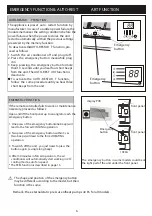
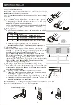
The piping  can  be  run  in the 3 directions indicated by

numbers  in  the  picture  . When  the  piping  is  run  in 

direction 1or3, cut a notch along the groove on the side 

of the indoor unit with a cutter.

Run the piping in the direction of the wall hole and bind 

the  copper  pipes , the  drain pipe and the  power cables 

together with the tape with the drain pipe at the bottom, 

so that water can flow freely.

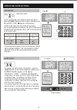
    1.   Remove the indoor unit pipe cap (check that there is 

          no debris inside).

    2.   Insert  the fare nut and create a flange at the extreme 

          end of the connection pipe.

    3.   Tighten  the  connections  by  using  two  wrenches 

          working in opposite directions

torque wrench

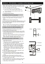
Indoor unit condensed water drainage

The indoor unit condensed water drainage is fundamen-

tal for the success of the installation.

1. Place the drain hose below the piping, taking care not 

    to create siphons.

2. The drain hose must slant downwards to aid drainage. 

3. Do not bend the drain hose or  leave  it  protruding or 

    twisted and do not put the end  of  it in water .  If  an 

    extension is connected to the drain hose , ensure that 

    it is lagged when it passes into the indoor unit.

4. If the piping is installed to the right, the pipes,  power 

    cable and drain hose must be lagged and secured onto 

    the rear of the unit with a pipe connection. 

1) Insert the pipe connection into the relative slot. 

2) Press to join the pipe connection to the base.  

YES

19

Refrigerant piping connection

Connections to the indoor unit

NO

NO

NO

YES

Extending the rolled pipe

Shape the connection pipe

 Do not remove the cap  from the pipe until connecting 

     it, to avoid dampness or dirt from entering.

 If the pipe is bent or pulled  too often , it  will become 

     stiff . Do  not  bend  the pipe more than three times at 

     one point.

 When extending the rolled pipe, straighten the pipe by 

     unwinding it gently as shown in the picture.

Summary of Contents for METH-16

Page 1: ...METH 16 USER AND INSTALLATION MANUAL METH 16 Julio 2021...

Page 2: ...Y PR E CA UT IONS NAMES OF PARTS INDOOR UNIT DISPLAY OPERATING INSTRUCTIONS PROTECTION INSTALLATION MANUAL MAINTENANCE TROUBLESHOOTING EMERGENCY FUNCTION AUTO RESTART FUNCTION REMOTE CONTROLLER 1 4 5...

Page 3: ...ging materials are recyclable and should be disposed of in the separate waste bins Take the air conditioner at the end of its useful life to a special waste collection centre for disposal Only use the...

Page 4: ...for any other purpose such as for drying clothes cooling food etc The packaging materials are recyclable and should be disposed of in the sparate waste bins Take the air conditioner at the end of its...

Page 5: ...not leave windows or doors open for long when the air conditioner is operating Do not direct the airflow onto plants or animals A long direct exposition to the flow of cold air of the conditioner cou...

Page 6: ...am of the appliance and may not correspond to the appearance of the units that have been purchased No Description 13 Air outlet grille Terminal block cover 14 gas valve 15 liquid valve 16 11 Indoor un...

Page 7: ...d Function POWER This symbol appears when the unit is power on 1 2 3 4 5 Temperature display if present Error code 1 Lights up during Timer operation when the air conditioner is operational 2 Displays...

Page 8: ...press of the emergency button within 3 sec two beeps will lead to the forced HEATING operation 3 To switch off the unit you just need to press the button again a single long beep 4 After 30 minutes in...

Page 9: ...he preset temperature in the shortest time In COOL mode the unit will give the maximum cooling temperature with 16 high fan speed In HEAT ode the unit willgive the maximum heating temperature with 31...

Page 10: ...ry Heat Mid High Sleep Swing Timer OFF Timer Fan C h ON MODE FAN S LE E P E CO TIME R S WING TUR B O HE ALTHY DIS PLAY S WING 6 8 1 2 3 5 12 13 10 10 4 7 9 6 5 8 2 1 3 4 MID AUTO SWING X HIGH LOW DRY...

Page 11: ...r MIDDLE FAN SPEED indicator or or HIGH FAN SPEED indicator QUIET or or SLEEP indicator or AUTO or or FLAP SWING indicator 15 SUPER indicator 16 17 HEALTHY indicator T IME R ON or or T IME R OF F or H...

Page 12: ...toward the Air conditioner 2 Check that there are no objects between the remote control and the Signal receptor in the indoor unit 3 Never leave the remote controller exposed to the rays of the sun 4...

Page 13: ...dist ributed in the room It is possible to position the direction of the air in the optimal In cooling mode orient the flaps in horizontal direction In heating mode orient the flaps downward as the w...

Page 14: ...ioner adjust the temperature 1 the speed 2 and the direction of the air flow 3 by pressing the button indicated HEAT The heating function allows the air conditi oner to heat the room To activate the h...

Page 15: ...ld be power off Press TIMER at the fist time set the temperature with pressing the button or Press TIMER at the second time set the rest time with pressing the button or Press TIMER at the third time...

Page 16: ...NG or HEATING This function reduces the humid ity of the air to make the room more comfortable To set the DRY mode Press MODE untill DRY appears in the display An automatic function of alternating coo...

Page 17: ...mperature is gradually decreased by 2 during the first 2 hours of operation After 10 hours running in sleep mode the air conditio ner is swicthed off automatically 15 FEEL MODE POWER SLEEP TIMER RUN I...

Page 18: ...ition models The unit does not operate immediately if it is turned on after being turned off or after changing the mode during operation this is a normal self protection action you need wait for about...

Page 19: ...ed mm showing in the picture 50 0 Outdoor unit Indoor unit be less than 5m Height should Outdoor unit Indoor unit be less than 5m Height should Installation Diagram 17 INDOOR UNIT OUTDOOR UNIT The pur...

Page 20: ...pping screws 5 Be sure that the rear panel has been fixed firmly enough to withstand the weight 1 Make the piping hole 55 in the wall at a slight downward slant to the outdoor side 2 Insert the piping...

Page 21: ...ace the drain hose below the piping taking care not to create siphons 2 The drain hose must slant downwards to aid drainage 3 Do not bend the drain hose or leave it protruding or twisted and do not pu...

Page 22: ...unit The outdoor unit should be installed on a solid wall and fastened securely The following procedure must be observed before co nnecting the pipes and connecting cables decide which is the best pos...

Page 23: ...kage as the flange could be damaged 3 The surest system consists in tightening the connecti on by using a fix wrench and a torque wrench in this case use the table on page 23 vacuum pump service port...

Page 24: ...acuum pump hose 8 Replace and tighten all the caps on the valves 3 way valve diagram connect to indoor unit open position spindle service port cap Connect to outdoor unit Valve core needle INSTALLA TI...

Page 25: ...g m 20g m 30g m 30g m 30g m 5m 5m 5m 5m 5m 5m 5m R22 MODEL capacity Btu h 7k 9k 12k 15 18k 22 24k 28 30k 36k Liquid pipe diameter Gas pipe diameter Lenght of pipe with standard charge Maximum distance...

Page 26: ...inal block For different models the wiring diagram may be different Please refer to the wiring diagrams pasted on the indoor unit and outdoor unit respectively On indoor unit the wiring diagram is pas...

Page 27: ...5mm 2 1 0mm 2 1 5mm 2 1 5mm 2 1 5mm 2 1 5mm 2 1 0mm 2 1 5mm 2 1 0mm 2 1 5mm 2 1 0mm 2 0 75mm 2 1 5mm 2 1 0mm 2 1 5mm 2 1 0mm 2 1 5mm 2 1 5mm 2 1 0mm INVERTER TYPE MODEL capacity Btu h AWG16 AWG18 AWG1...

Page 28: ...ife it till its greatest stroke and then unhooking it from the hinges to make the cleaning easier 2 Clean the indoor unit using a cloth with the water not higher than 40 and neutral soap Never use agg...

Page 29: ...This occurs when the air in the room becomes very cold for example in the COOLING or DEHUMIDIFYING DRY modes This noise is made by the expansion or contraction of the front panel due to variations in...

Reviews: