


MViP User's Guide
Page - 4
Revision 1.1
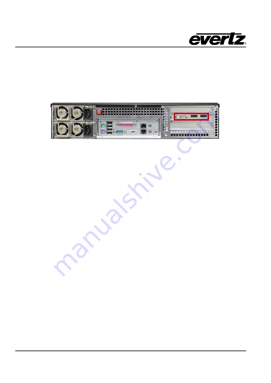
8. Connect the MViP to display(s) using customer supplied DVI cables. For a single monitor, the MViP
has a built in DVI connector.
When using the MViP in dual head mode, use the supplied Display Port to DVI adapter cable.
Connect the other end of the DVI to a DVI display. Make sure the display is powered on before turning
on the MViP. The MViP has the ability to auto-detect the highest resolution on the monitor and set its
output to that resolution. Please note that this is only possible while using a display that uses the EDID
video resolutions table as described by VESA.
9. Switch the unit on using the power switch at the front of the frame. First, remove the cover plate by
loosening the Pem screws on the left and right sides of the frame.
10. The MViP will now turn on and will run through its opening sequence for approximately 1 minute.
1.2.
CONFIGURING THE MVIP SYSTEM AND NETWORK SETTINGS
1. The user must complete the hardware setup in section 1.1 before configuring the MViP network
settings.
2. Once the MViP has been powered on, the user will see a mouse pointer in the center of
Display 1
(if
both displays are connected). If the user does not see the mouse pointer on the screen, double check
the setup in section 1.1 to ensure that the monitor and cable are connected correctly.
3. The MViP IP addresses must be set for the management port and the data port. To configure the
network addresses perform the following steps:
a. Using the attached keyboard, press “CTRL, ALT, F1” at the same time.
b. The display will show an “mvip login” prompt – enter “admin” for both user id and the
password.


