HD9690 Series HDTV Graticule Generator Manual
INSTALLATION
Revision 1.5
Page 2-3
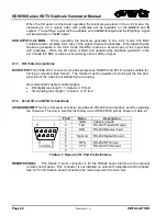
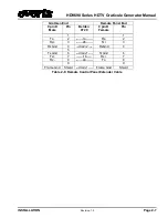
Pin #
Name
Description
1
GND
Chassis ground
2
TX-
RS-422 Transmit – Output
3
RX+
RS-422 R Input
4
5
6
GND
Transmit ground
7
TX+
RS-422 Tr Output
8
RX-
RS-422 Receive – Input
9
Table 2-2: Remote Panel Port Pin Definitions
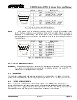
GPI/O
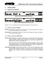
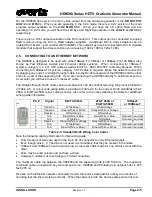
This female 9 pin D connector provides 8 General Purpose Opto-isolated inputs
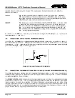
(GPIs). Table 2-3 shows the pin definitions of the GPIO connector. Figure 2-3 shows a
schematic of the GPI circuitry. See section 2.6 for more information on connecting the
General Purpose inputs and outputs. The GPIs are used as an alternate way to load 8 of
the user presets
Pin #
Name
Description
1
GPI1
User preset 0
2
GPI2
User preset 1
3
GPI3
User preset 2
4
GPI4
User preset 3
5
GPI5
User preset 4
6
GPI6
User preset 5
7
GPI7
User preset 6
8
GPI8
User preset 7
9
GND
GND
Table 2-3: GPI/O Port Pin Definitions
2.1.5. Ethernet Network Connections
ETHERNET
This RJ-45 connector is an Ethernet port used for high speed FTP firmware upgrades.
See section 2.5 for information on connecting to an Ethernet network. See section 5.3.1 for
information on upgrading firmware using FTP.
2.2.
MOUNTING
The HD9690 is equipped with rack mounting angles and fit into a standard 19 inches by 1.75 inches
(483 mm x 45 mm) rack space. The mounting angles may be removed if rack mounting is not desired.
2.3.
POWER REQUIREMENTS
Power requirements are 100 to 240 volts AC at 50 or 60 Hz. The HD9690 has a universal power
supply that automatically senses the input voltage. Power should be applied by connecting a 3-wire
grounding type power supply cord to the power entry module on the rear panel. The power cord should
be minimum 18 AWG wire size; type SVT marked VW-1, maximum 2.5 m in length.

