background image


7800EMR-ALINK2 

User Manual 


© Copyright 2017 
 

EVERTZ MICROSYSTEMS LTD. 

5292 John Lucas Drive, 
Burlington, Ontario,  
Canada L7L 5Z9 
 
Phone: 

+1 905-335-3700 

Sales: 

[email protected] 

Fax: +1 905-335-3573 

Tech Support:  [email protected]  

Fax: +1 905-335-7571 

Web Page: 

http://www.evertz.com


Version 1.0, November 2017 

 
The material contained in this user manual consists of information that is the property of Evertz Microsystems and is intended solely for the use of 
purchasers of the 7800EMR-ALINK2  product.  Evertz Microsystems expressly prohibits the use of this guide  for any purpose other than the 
operation of the contained in this reference guide consists of information that is the property of Evertz Microsystems and is intended solely for the 
use of purchasers of the 7800EMR-ALINK2 product.  Due to on going research and development, features and specifications in this manual are 
subject to change without notice. 
 
All rights reserved.  No part of this publication may be reproduced without the express written permission of Evertz Microsystems Ltd.  Copies of 
this manual can be ordered from your Evertz dealer or from Evertz Microsystems.


Summary of Contents for 7800EMR-ALINK2

Page 1: ...e 7800EMR ALINK2 product Evertz Microsystems expressly prohibits the use of this guide for any purpose other than the operation of the contained in this reference guide consists of information that is the property of Evertz Microsystems and is intended solely for the use of purchasers of the 7800EMR ALINK2 product Due to on going research and development features and specifications in this manual ...

Page 2: ...This page left intentionally blank ...

Page 3: ...hird grounding prong The wide blade or the third prong is provided for your safety If the provided plug does not fit into your outlet consult an electrician for replacement of the obsolete outlet Protect the power cord from being walked on or pinched particularly at plugs convenience receptacles and the point where they exit from the apparatus Only use attachments accessories specified by the manu...

Page 4: ... Class A digital device pursuant to Part 15 of the FCC Rules These limits are designed to provide reasonable protection against harmful interference when the equipment is operated in a commercial environment This equipment generates uses and can radiate radio frequency energy and if not installed and used in accordance with the instruction manual may cause harmful interference to radio communicati...

Page 5: ... SERIAL MENU 9 5 1 NETWORK CONFIGURATION 10 5 2 SNMP CONFIGURATION 10 5 3 AUDIO CONFIGURATION 10 5 4 A LINK MODE CONFIGURATION 11 5 5 REFERENCE CONFIGURATION MENU 11 5 6 SHOW BOARD INFORMATION 11 5 7 SHOW SFP SETUP 11 5 8 ENGINEERING DEBUG UTILITY 11 5 9 SAVE TO FLASH AND REBOOT 11 6 VISTALINK PRO CONFIGURATION 13 6 1 DUAL PORT MODE 13 6 1 1 GENERAL 13 6 1 2 A LINK CONTROL 15 6 1 3 TDM CONTROL 17 ...

Page 6: ...K Monitor Status 20 Figure 6 5 Dual Port Mode VistaLINK Audio Mono Config 21 Figure 6 6 Dual Port Mode VistaLINK Audio Stereo Config 23 Figure 6 7 Dual Port Mode VistaLINK Audio Channel Faults 25 Figure 6 8 Dual Port Mode VistaLINK Audio Channel Pair Faults 27 Figure 6 9 Redundancy Mode VistaLINK General 29 Figure 6 11 Redundancy Mode VistaLINK ALINK 31 Figure 6 12 Redundancy Mode VistaLINK TDM Co...

Page 7: ...ffered by Evertz in relation to this product is the Evertz standard limited warranty stated in the sales contract or order confirmation form Although every attempt has been made to accurately describe the features installation and operation of this product in this reference guide no warranty is granted nor liability assumed in relation to any errors or omissions unless specifically undertaken in t...

Page 8: ...7800EMR ALINK2 User Manual Page iv Revision 1 0 This page left intentionally blank ...

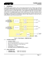
Page 9: ...h path The 7800EMR ALINK2 utilizes a video reference locked to the system reference to ensure the signals are properly locked for transporting the audio seamlessly back and forth across TDM and A LINK Reference is provided via the 7800 frame reference inputs optionally the card does have an external reference that can be selected and used Figure 1 1 Block Diagram 7800EMR ALINK2 1 1 FEATURES BENEFI...

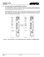
Page 10: ...Input 2 serves as the backup input on both A Link port 1 2 In Redundant Mode A Link Port 1 serves as the main A Link port and Input 1 as the main TDM Input A Link Port 2 serves as the backup A Link Port and as the backup TDM Input In this mode the 2nd TDM input on each A Link port is not operational All TDM outputs remain operational in either Dual Port Mode or Redundant Mode Figure 1 2 Redundant ...

Page 11: ... 2 2 A LINK INPUTS OUTPUTS Number of A LINK Inputs 2 Number of A LINK Outputs 2 Connector SFP10G TR85 A A Link SFP Optical Transceiver 850nm MMF 2 3 CONTROL Ethernet 1 x RJ45 2 4 REFERENCE External Reference Inputs 1 x DIN Frame Reference Inputs 2 x BNC depends on the frame 2 5 FRAMES Frame and Slot Occupancy 7800FR Frame with 1 slot occupancy 7801FR Frame with 1 slot occupancy 7800FR QT Frame wit...

Page 12: ...7800EMR ALINK2 User Manual Page 4 Revision 1 0 This page left intentionally blank ...

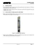
Page 13: ...t in the frame Each rear plate can house one 7800EMR ALINK2 module 3 1 INSTALLATION OF 7800EMR ALINK2 ON 7800FR FRAME Step 1 Install the 7800EMR ALINK2 rear plate to the 7800 frame with screws provided and make sure the orientation of the rear plate is as shown in Figure 3 1 Figure 3 1 7800EMR ALINK2 Rear Plate Step 2 Insert the 7800EMR ALINK2 module in the 7800FR Frame and make sure the orientati...

Page 14: ...7800EMR ALINK2 User Manual Page 6 Revision 1 0 This page left intentionally blank ...

Page 15: ...rocesses Figure 4 1 shows the card edges and describes the expected behavior of each component Component Description A Link Presence Red Green TDM Input Red Green Reference Detection Red Reference Lost Green Reference Locked Rotary Switch Switched the display to view firmware version IP address and temperature Table 4 1 Description of 7800EMR ALINK2 Card Edge Figure 4 1 Front Card Edges of 7800EMR...

Page 16: ...7800EMR ALINK2 User Manual Page 8 Revision 1 0 This page left intentionally blank ...

Page 17: ...B9 cable between the COM port on the 7800EMR ALINK2 J6 and the computer Start the terminal program and configure the ports settings with the parameters in Figure 5 1 Figure 5 1 COM Port Settings After establishing serial communication Main Menu will appear in the terminal window as in Figure 5 2 Figure 5 2 Main Menu Prompt ...

Page 18: ...ess Allows the user to set port address between 0 254 Set Sample Rate Allows the user to set SRC to 48KHz 96KHz Audio TDM Fault Status View Fault Configuration Displays the fault for Silence Over Amplitude Same Anti phase Loss and Non PCM Set Fault Enable Allows the user to enable the above faults per channel or range Set Fault Threshold Allows the user to set threshold for silence over amplitude ...

Page 19: ...INK MODE CONFIGURATION Redundancy Mode Allows the user to select Redundancy Mode Dual Port Mode Allows the user to select Dual Port Mode 5 5 REFERENCE CONFIGURATION MENU View Reference Info Allows the user to view status of Reference Set Primary Reference Allows the user to set Ref 1 or Ref 2 as primary reference Set Reference input 2 source Allows the user to set the reference source to be the MI...

Page 20: ...7800EMR ALINK2 User Manual Page 12 Revision 1 0 This page left intentionally blank ...

Page 21: ... card and appropriate Jar file Open VistaLINK PRO and click on the refresh tree icon Select the IP address of 7800EMR ALINK2 and right click to View Configuration Depending on which mode the 7800EMR ALINK2 is set to the tab menu options in VistaLINK PRO differ slightly In section 6 1 and 6 2 both dual port mode and redundancy mode tab menus will be outlined respectively 6 1 DUAL PORT MODE When the...

Page 22: ...eset the Drop or Error count of the reference Fail Safe Mode Allows to configure the Reference fail safe mode Fixed Single Swap or Auto Mode Frame Ref Error Count Shows the Error count of the Reference Reset Error Count Button used to reset the Frame Reference Error Count Port 2 Drop Count Displays the Drop or Error Count of the Reference Port 2 Reset Drop Count Button is used to reset the Drop or...

Page 23: ...7800EMR ALINK2 User Manual Revision 1 0 Page 15 6 1 2 A LINK CONTROL The A Link Control section displays the status control and A Link Tone Generator Figure 6 2 Dual Port Mode VistaLINK ALINK ...

Page 24: ...t if the A Link either generates or receives a Sync reference Show A Link TG Channel Allows the user to select to which pair of A Link channels to configure Apply Button Apply button allows the user to copy the settings of channel 1 to rest of the mono channels ALINK Tone Generator Channel 1 2 A Link Tone Generator Option to enable or disable tone generator per channel A Link TG Frequency Option t...

Page 25: ...7800EMR ALINK2 User Manual Revision 1 0 Page 17 6 1 3 TDM CONTROL The TDM Control section displays the TDM Status and TDM Tone Generator Figure 6 3 Dual Port Mode VistaLINK TDM Control ...

Page 26: ...gnal on TDM Input 1 of A Link Port 2 TDM Input Reset Error Count 1 Button is used to reset the Error Count of the TDM Signal TDM Input 2 of A Link Port 1 TDM Input Present 2 Displays whether the TDM Signal is detected on TDM Input 2 of A Link Port 1 TDM Input SID Present 2 Displays whether the TDM Signal has Source ID or not TDM Input SID IP Address 2 Displays the IP Address of the TDM Source TDM ...

Page 27: ...DM Input Present 1 of A Link Port 2 Option to enable the trap for TDM presence for port 1 Audio TDM Input Errored 1 of A Link Port 2 Option to enable the trap for TDM Error for port 1 and 2 Audio TDM Input Present 2 of A Link Port 2 Option to enable the trap for TDM presence for port 1 2 Audio TDM Input Errored 2 of A Link Port 2 Option to enable the trap for TDM Error for port 1 and 2 TDM Input T...

Page 28: ...NK Port 1 2 Show Channels for TDM A Link Allows the user to select the channels to see the status of TDM A Link and Audio Signal Levels Audio TDM Signal Present Displays whether the TDM signal is present Audio A Link Signal Present Displays whether the A Link signal is present Audio TDM Signal Level Displays the Audio TDM signal Level Audio TDM Signal Level Displays the Audio TDM signal Level Audi...

Page 29: ... User Manual Revision 1 0 Page 21 6 1 5 AUDIO MONO CONFIG The Audio Mono Config section allows the user to set the audio fault threshold for TDM and A Link ports Figure 6 5 Dual Port Mode VistaLINK Audio Mono Config ...

Page 30: ... declared over TDM Over Reset Duration Option to check over duration for this many sec before the fault is reset A Link Audio Fault Definition for Channel 1 2 of Port 1 2 Show TDM Fault Definition Channel Allows the user to select the mono channels to set the fault definitions Apply Button Apply button is to set the mono channel 1 settings to rest of the mono channels A Link Loss Reset Duration Op...

Page 31: ...is to set the TDM stereo channel 1 2 settings to rest of the stereo channels TDM Pair Phase Reversal Level Sets the ratio of the pair at which it is declared out of phase TDM Pair Reversal Duration Sets the duration before the signal is declared out of phase TDM Pair Phase Reversal Reset Duration Sets the duration before the phase detection begins monitoring again TDM Pair Mono Level Sets the rati...

Page 32: ... Level Sets the ratio of the pair at which it is declared out of phase A Link Pair Reversal Duration Sets the duration before the signal is declared out of phase A Link Pair Phase Reversal Reset Duration Sets the duration before the phase detection begins monitoring again A Link Pair Mono Level Sets the ratio of the pair at which it is declared mono A Link Pair Mono Duration Sets the duration befo...

Page 33: ...l Faults Show TDM Audio Fault Channels Allows the user to select the TDM channels to enable the traps Apply Button Apply button is to set the channel 1 settings to rest of the TDM channels TDM Trap Enable For A Link Port 1 2 Audio Channel Loss Option to enable the trap for audio channel loss Audio Channel Silent Option to enable the trap for audio channel silent Audio Channel Over Option to enable...

Page 34: ...A Link Trap Enable For A Link Port 1 2 Audio Channel Loss Option to enable the trap for audio channel loss Audio Channel Silent Option to enable the trap for audio channel silent Audio Channel Over Option to enable the trap for audio channel over A Link Fault Status For A Link Port 1 2 Audio Channel Loss Option to display whether the audio is Lost Audio Channel Silent Option to display whether the...

Page 35: ...annels to enable traps on Apply Button The apply button applies the channel 1 settings to the rest of the TDM channels Trap Enable Phase Reversal Allows the user to enable traps to be sent out when a phase reversal fault is detected on the selected audio pair Trap Status Phase Reversal Status monitor displays fault condition on the audio pairs Green indicates no faults while red indicates a trigge...

Page 36: ...of the A Link channels Trap Enable Phase Reversal Allows the user to enable traps to be sent out when a phase reversal fault is detected on the selected audio pair Trap Status Phase Reversal Status monitor displays fault condition on the audio pairs Green indicates no faults while red indicates a triggered fault condition Trap Enable Mono Allows the user to enable traps to be sent out when a fault...

Page 37: ...s to select the reference Standard from NTSC PAL or Auto Present Displays whether the Video reference is Present or Absent Video Standard Displays the standard of the Video Reference Primary Reference Source Allows to select the Primary Reference from Reference Port 1 or Reference Port 2 Frame Ref Port In Use Shows which Reference Port is in use Reference Port 1 or Reference Port 2 Ref Input 2 Sou...

Page 38: ...ference Port 2 Reset Drop Count Button is used to reset the Drop or Error count of the reference Card Status Card Type Displays the name of the card Card A Link Mode Displays which mode the card is current set to Card Channel Pair Count Displays the Stereo Channel of the Card Card Channel Count Displays the Mono Channel of the Card Frame Ref Trap Status Frame Ref Status 1 Raises a trap when a refe...

Page 39: ...7800EMR ALINK2 User Manual Revision 1 0 Page 31 6 2 2 A LINK CONTROL The A Link Control section displays the status control and A Link Tone Generator Figure 6 10 Redundancy Mode VistaLINK ALINK ...

Page 40: ...y instance A Link Sync Option Allows the user to select if the A Link either generates or receives a Sync reference A Link Tone Generator Show A Link TG Channel Allows the user to select to which pair of A Link channels to configure Apply Button Apply button allows the user to copy the settings of channel 1 to rest of the mono channels A Link Tone Generator Option to enable or disable tone generat...

Page 41: ...7800EMR ALINK2 User Manual Revision 1 0 Page 33 6 2 3 TDM CONTROL The TDM Control section displays the TDM Status and TDM Tone Generator Figure 6 11 Redundancy Mode VistaLINK TDM Control ...

Page 42: ...gnal on TDM Input 1 of A Link Port 2 TDM Input Reset Error Count 1 Button is used to reset the Error Count of the TDM Signal TDM Input 2 of A Link Port 1 TDM Input Present 2 Displays whether the TDM Signal is detected on TDM Input 2 of A Link Port 1 TDM Input SID Present 2 Displays whether the TDM Signal has Source ID or not TDM Input SID IP Address 2 Displays the IP Address of the TDM Source TDM ...

Page 43: ...o TDM Input Trap Enable Audio TDM Input Present 1 of A Link Port 1 Option to enable the trap for TDM presence for port 1 Audio TDM Input Errored 1 of A Link Port 1 Option to enable the trap for TDM Error for port 1 and 2 Audio TDM Input Present 1of A Link Port 2 Option to enable the trap for TDM presence for port 1 and 2 Audio TDM Input Errored 1 of A Link Port 2 Option to enable the trap for TDM ...

Page 44: ... Status TDM A LINK Channel 1 of A Link Port 1 2 Show Channels for TDM A Link Allows the user to select the channels to see the status of TDM A Link and Audio Signal Levels Audio TDM Signal Present Displays whether the TDM signal is present Audio A Link Signal Present Displays whether the A Link signal is present Audio TDM Signal Level Displays the Audio TDM signal Level Audio A Link Signal Level D...

Page 45: ...User Manual Revision 1 0 Page 37 6 2 5 AUDIO MONO CONFIG The Audio Mono Config section allows the user to set the audio fault threshold for TDM and A Link ports Figure 6 13 Redundancy Mode VistaLINK Audio Mono Config ...

Page 46: ...declared over TDM Over Reset Duration Option to check over duration for this many sec before the fault is reset A Link Audio Fault Definition for Channel 1 2 of Port 1 2 Show A Link Fault Definition Channel Allows the user to select the mono channels to set the fault definitions Apply button Apply button is to set the mono channel 1 settings to rest of the mono channels A Link Loss Reset Duration ...

Page 47: ...r Manual Revision 1 0 Page 39 6 2 6 AUDIO STEREO CONFIG The Audio Stereo Config section allows the user to set the audio fault threshold for TDM and A Link ports Figure 6 14 Redundancy Mode VistaLINK Audio Stereo Config ...

Page 48: ...eclared mono TDM Pair Mono Reset Duration Sets the duration before the mono detection begins monitoring again A LINK Audio Fault Definition for Port 1 2 Show A LINK Fault Definition Channel Allows the user to select the A Link stereo channel to set the fault definitions Apply Button Apply button is to set the A Link stereo channel 1 2 settings to rest of the stereo channels A LINK Pair Phase Rever...

Page 49: ...Mode VistaLINK Audio Channel Faults Show TDM Audio Fault Channels Allows the user to select the TDM channels to enable the traps Apply Button Apply button is to set the channel 1 settings to rest of the TDM channels TDM Trap Enable For A Link Port 1 2 Audio Channel Loss Option to enable the trap for audio channel loss Audio Channel Silent Option to enable the trap for audio channel silent ...

Page 50: ...display whether the audio is over A Link Trap Enable For A Link Port 1 2 Audio Channel Loss Option to enable the trap for audio channel loss Audio Channel Silent Option to enable the trap for audio channel silent Audio Channel Over Option to enable the trap for audio channel over A Link Fault Status For A Link Port 1 2 Audio Channel Loss Option to display whether the audio is Lost Audio Channel Si...

Page 51: ...els to enable traps on Apply Button The apply button applies the channel 1 settings to the rest of the TDM channels Trap Enable Phase Reversal Allows the user to enable traps to be sent out when a phase reversal fault is detected on the selected audio pair Trap Status Phase Reversal Status monitor displays fault condition on the audio pairs Green indicates no faults while red indicates a triggered...

Page 52: ...he A Link channels Trap Enable Phase Reversal Allows the user to enable traps to be sent out when a phase reversal fault is detected on the selected audio pair Trap Status Phase Reversal Status monitor displays fault condition on the audio pairs Green indicates no faults while red indicates a triggered fault condition Trap Enable Mono Allows the user to enable traps to be sent out when a fault is ...

Page 53: ...witch negotiation to complete then it is possible that your JAR file may be old or missing To perform a JAR update ensure that all VLPro clients are closed those clients which are not closed will automatically be disconnected as soon as the VLPro server is restarted Maximize the VLPro Server window from the Windows task bar select Help Apply Update Product from the menu Figure 7 1 VistaLINK PRO Se...

Page 54: ...arting the server Figure 7 3 VistaLink PRO Restart You Alarm Server By clicking Yes server will automatically restart but it is normal for the startup to take marginally longer while each individual update is being applied Once complete you may restart the VLPro Clients As the clients restarts you will experience a short delay while the update is applied A prompt will appear confirming that the up...

Page 55: ...re the x s represent the module s IP Address 5 Press ENTER when prompted for a Username And again when prompted for a Password 6 At the ftp prompt type hash toggles number sign printing for each data block that is transferred 7 At the ftp prompt type put x bin where x represents the name of the firmware bin Note If the firmware file is not local to where you are performing the FTP then include the...

Page 56: ...7800EMR ALINK2 User Manual Page 48 Revision 1 0 Figure 8 2 Sample FTP Upgrade Window ...

Reviews: