7800 MultiFrame Manual
7800FC VistaLINK
®
Frame Controller
Revision 1.0
Page-7
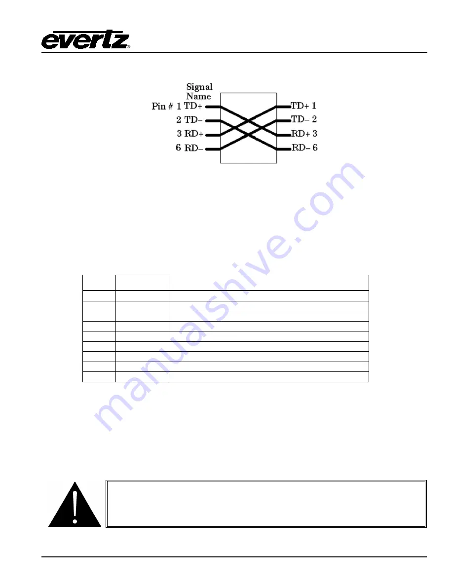
If you are building a “crossover” cable you must wire it according to Figure 2-4:
Figure 2-4: Crossover Cable Wiring Diagram
2.3.2. GPI/O Connections
GP I/O:
A 9 pin female ‘D’ connector for connection to external devices. (
Currenlty this port is not used.
)
2.3.3. Serial I/O Connections
SERIAL I/O:
A 9 pin female 'D' connector for connection to a computer. (
Currently this port is not used.
)
Pin #
Name
Description
1
GND
Chassis ground
2
Tx
RS-232 Transmit Output
3
Rx
RS-232 Receive Input
4
5
Sig Gnd
RS-232 Signal Ground
6
7
RTS
RS-232 RTS Input
8
CTS
RS-232 CTS Output
9
Table 2-2: Serial I/O Connector Pin Definitions
2.4.
REPLACING THE BATTERY
The Frame Controller is fitted with a 3V Lithium battery type CR2032. This battery is used to power non-
volatile memory of some of the frame controller’s parameters while power is removed from the frame.
Before attempting to change the battery remove power from the 7800FC card.
CAUTION
Danger of explosion if battery is incorrectly replaced.
Replace only with the same or equivalent type.


