7706LT
Extended L-Band RF Fiber Transmitter
Revision 1.1
Page - 9
4.
STATUS INDICATORS
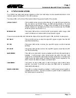
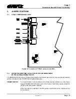
The 7706LT has eight LED status indicators on the front card edge to show operational status of the
card at a glance. See Figure 5-1 for LED locations.
Two large LEDs on the front of the board indicate the general health of the module:
LOCAL FAULT:
This red LED will be on during the absence of a valid RF input signal (too
low, too high or out of AGC range), an LNB short/overload, or if a local
internal power fault exists (i.e.: a blown fuse). Whether or not this LOCAL
FAULT indication is reported to the frame may be selected by the FRAME
STATUS jumper (see section 5.1).
MODULE OK:
This green LED will be on when the RF input signal is within range, LNB
power conditions are normal and the board power is good.
There are six small LEDs that indicate the status of the input RF signal, LNB, and AGC mode signals.
RF HIGH:
This red LED will be on when the input RF signal is higher than the RF
high threshold setting.
RF OK:
This green LED will be on when the input RF signal is within threshold
settings.
RF LOW:
This yellow LED will be on when the input RF signal is lower than the RF
low threshold setting.
GAIN MODE:
This LED is on when AGC mode is enabled and off when Manual mode is
enabled. It will be green when power levels are within the AGC hold
range and a constant RF output level is being maintained. It will be red if
power levels are either above or below the power levels required for the
AGC circuit to be able to maintain a constant level.
LNB MODE:
This LED is on when LNB power is ON. It will green when LNB is active
and OK (no short). It will be red when an LNB short or overload is
detected (fault present).
SQUELCH MODE:
This LED is on when squelch is enabled. It will be green when squelch is
enabled but not active. It will be red when squelch mode is enabled and
the output signal is squelched.


