background image


570REM-RX8-10GE 

                                                                                                                  User manual 


Revision 1.0


Page iii 


FIGURES 


Figure 


1-1 : 570REM-RX8-10GE Block Diagram ........................................................................... 1


Figure 


2-1 : 570REM Rear Plate .................................................................................................... 3


Figure 


4-1 : WebEASY

® 

- Login Menu ........................................................................................... 7


Figure 


4-2 : WebEASY

® 

- 570REM-RX8-10GE Main Menu............................................................ 8


Figure 


4-3 : WebEASY

® 

- System (Part 1) ..................................................................................... 9


Figure 


4-4 : WebEASY

® 

- System (Part 2) ................................................................................... 11


Figure 


4-5 : WebEASY

® 

- Product Features ................................................................................. 13


Figure 


4-6 : WebEASY

® 

- DIN Output Control .............................................................................. 14


Figure 


4-7 : WebEASY

® 

- IP Output Control ................................................................................. 15


Figure 


4-8 : WebEASY

® 

- IP Input Control ................................................................................... 17


Figure 


4-9 : WebEASY

® 

- Breakaway Audio Input Control ........................................................... 19


Figure 


4-10 : WebEASY

® 

- Decoder Control ................................................................................ 20


Figure 


4-11 : WebEASY

® 

- RTP and Master PCR Control ........................................................... 23


Figure 


4-12 : WebEASY

® 

- IP Input Monitor ................................................................................. 25


Figure 


4-13 : WebEASY

® 

- Decoder Program Monitor ................................................................. 26


Figure 


4-14 : WebEASY

® 

- System Notify .................................................................................... 28


Figure 


4-15 : WebEASY

® 

- Decoder Notify ................................................................................... 29


Figure 


5-1 : WebEASY

® 

- Upgrade Button on Top Menu Bar ....................................................... 31


Figure 


5-2 : WebEASY

® 

- Firmware Upgrade Menu ..................................................................... 31


Figure 


5-3 : WebEASY

® 

- Firmware Upgrade Menu\Selecting Firmware File ............................... 32


Summary of Contents for 570REM-RX8-10GE

Page 1: ...V Version 1 0 December 2018 The material contained in this manual consists of information that is the property of Evertz Microsystems and is intended solely for the use of purchasers of the 570REM RX8 10GE Evertz Microsystems expressly prohibits the use of this manual for any purpose other than the operation of the 570REM RX8 10GE All rights reserved No part of this publication may be reproduced w...

Page 2: ...This page left intentionally blank ...

Page 3: ...rd grounding prong The wide blade or the third prong is provided for your safety If the provided plug does not fit into your outlet consult an electrician for replacement of the obsolete outlet Protect the power cord from being walked on or pinched particularly at plugs convenience receptacles and the point where they exit from the apparatus Only use attachments accessories specified by the manufa...

Page 4: ...ly to cause harmful interference in which case the user will be required to correct the interference at his own expense INFORMATION TO USERS IN THE U S A NOTE FCC CLASS A DIGITAL DEVICE OR PERIPHERAL This equipment has been tested and found to comply with the limits for a Class A digital device pursuant to Part 15 of the FCC Rules These limits are designed to provide reasonable protection against ...

Page 5: ...ffered by Evertz in relation to this product is the Evertz standard limited warranty stated in the sales contract or order confirmation form Although every attempt has been made to accurately describe the features installation and operation of this product in this manual no warranty is granted nor liability assumed in relation to any errors or omissions unless specifically undertaken in the Evertz...

Page 6: ...570REM RX8 10GE User Manual Revision 1 0 This page left intentionally blank ...

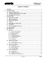
Page 7: ... 7 4 1 SYSTEM 9 4 1 1 Control Port Configuration 9 4 1 2 Data Port Configuration 9 4 1 3 Data Port Monitor 10 4 1 4 SFP Monitor 11 4 1 5 Temperature Monitor 11 4 1 6 Configuration Management 11 4 1 7 Time Management 12 4 1 8 Genlock 12 4 1 9 Card Control 12 4 2 PRODUCT FEATURES 13 4 2 1 License Control 13 4 2 2 Product Features Supported 13 4 3 DIN OUTPUT CONTROL 14 4 3 1 Output Control 14 4 3 2 S...

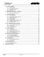
Page 8: ...ence PCR Control 22 4 7 7 Decoder Lip Sync Control 22 4 7 8 Decoder Control 22 4 8 RTP AND MASTER PCR CONTROL 23 4 8 1 PTP and Master PCR Control 23 4 8 2 PTP Control 23 4 8 3 Master PCR Control 24 4 9 IP INPUT MONITOR 25 4 9 1 Input Stream 25 4 9 2 Input IP Packet Monitor 26 4 9 3 IP Packet Drop Counter Clear 26 4 9 4 Jitter Measurement 26 4 10 DECODER PROGRAM MONITOR 26 4 10 1 Internal Decoder C...

Page 9: ...ntrol 14 Figure 4 7 WebEASY IP Output Control 15 Figure 4 8 WebEASY IP Input Control 17 Figure 4 9 WebEASY Breakaway Audio Input Control 19 Figure 4 10 WebEASY Decoder Control 20 Figure 4 11 WebEASY RTP and Master PCR Control 23 Figure 4 12 WebEASY IP Input Monitor 25 Figure 4 13 WebEASY Decoder Program Monitor 26 Figure 4 14 WebEASY System Notify 28 Figure 4 15 WebEASY Decoder Notify 29 Figure 5 ...

Page 10: ...570REM RX8 10GE User manual Page iv Revision 1 0 This page left intentionally blank ...

Page 11: ...70REM RX8 10GE can be managed via integrated HTTP web interface as well as SNMP management via Frame Controller Features Benefits 8x 3G HD SD or 2x UHD JPEG2000 decodes with 2xSDI decoded outputs per JPEG2000 decode Standards supported 3840x2160p 59 94 50 Quad Division or 2SI 1080p 59 94 50 Level A 1080i 59 94 50 720p 59 94 50 625i 50 and 525i 59 94 Support VSF TR 01 v2 4x groups of audio on SDI o...

Page 12: ...570REM RX8 10GE User manual Page 2 Revision 1 0 This page left intentionally blank ...

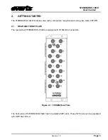
Page 13: ... with a companion rear plate and occupy two slots in 570FR 2 1 REAR AND FRONT PLATE The rear plate of 570REM RX8 10GE is equipped with 20 Mini Din connectors Figure 2 1 570REM Rear Plate The front plate of 570REM RX8 10GE has 12 available SFP slots These SFP slots can be populated with SFP10G TR13 A ...

Page 14: ...ng is required 1 570 Series Frame 2 570 Frame Controller 3 WebEASY using the 570FC frame controller with 570REM RX8 10GE installed in frame Before handling the card it is important to minimize the potential effects of static electricity It is therefore recommended that an ESD strap be worn Locate on the chassis 2 adjacent vacant slots Unpack the 570REM RX8 10GE and separate the rear panel from the...

Page 15: ... 3 3 SERIAL VIDEO OUTPUT Number of Outputs 16x SDI Connector DIN Rise and Fall Time Per SMPTE spec 3 4 IP INPUT Ethernet Interface 4 x 10GE SFP SFP Ethernet IP Signaling Multicast IGMP V2 V3 SSM Support 3 5 EMBEDDING OF HANC VANC 4x Groups Audio Pass through per encoder All type of VANC data pass through 3 6 ELECTRICAL Power 90W Voltage 12VDC EMI RFI Complies with FCC Part 15 Class A EU EMC direct...

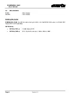
Page 16: ...70FR 3RU Chassis S570FR 1RU Chassis Ordering Information 570REM RX8 10GE 8x J2K Decoders driving 2x UHD or 8x 3G HD SD SDI output 4x 10GbE SFP Cages SFP sold separately SFP Modules SFP10G TR13 A 10GbE Optical SFP SFP10G TR85 A SFP Optical Transceiver 10Gbs 850nm MMF ...

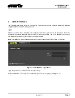
Page 17: ... the required network addresses it can be completely configured using the web interface For doing this simply type the IP address of the control port of the 570REM RX8 10GE module in the web browser Note Computer must be on the same Subnet in order to have communication with the module Figure 4 1 WebEASY Login Menu Login and password is root and evertz respectively On the web interface there are s...

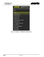
Page 18: ...570REM RX8 10GE User manual Page 8 Revision 1 0 Figure 4 2 WebEASY 570REM RX8 10GE Main Menu ...

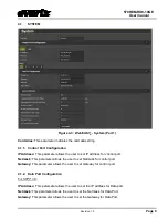
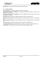
Page 19: ...IP address for control port Netmask This parameter allows the user to set Netmask for control port Gateway This parameter allows the user to set Gateway for control port 4 1 2 Data Port Configuration For SFPP 1 6 IP Address This parameter allows the user to set the IP address for Data port Netmask This parameter allows the user to set the Netmask for Data Port Gateway This parameter allows the use...

Page 20: ...e transmitted on this output Ethernet port unit is kbps Rx Frame Count This parameter indicates received Rx frames on this Ethernet port Rx CRC Error Frame Count This field indicates received Rx frames with CRC errors on this Ethernet port Rx Undersized Frame Count This field indicates received Rx undersized frames on this Ethernet port Tx Frame Count This parameter indicates received Tx frames on...

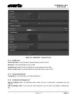
Page 21: ...ield indicates the received power level of SFP SFP Tx Power Level This field indicates the transmitted power level of SFP 4 1 5 Temperature Monitor Temperature This field shows the FPGA temperature 4 1 6 Configuration Management Export Configure File The download button allows the user to download a configuration file and export it Import Configure File The Choose file section allows the user to s...

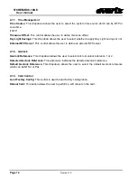
Page 22: ...External NTP Server This control allows the user to define an external NTP server 4 1 8 Genlock Genlock Reference This dropdown allows the user to select lock to Genlock reference 1 or 2 Detected Genlock Reference This parameter indicates the detected Genlock reference Default Genlock Reference This dropdown allows the user to select the default Genlock reference which can be NTSC or PAL 4 1 9 Car...

Page 23: ...lays the card serial number same as the card MIB control This is needed for the webpage Product Mac Address This parameter displays the card MAC address 4 2 2 Product Features Supported Product feature Name This parameter indicates the product features supported on this card Product feature Supported This parameter indicates the product support enabled disabled status ...

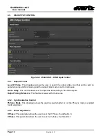
Page 24: ...de is set to continoues Frame Delay This control allows user to adjust the frame delay for the SDI outputs Output Timing Reference This feature is reserved for future use 4 3 2 Synchronization Control FS Sync Mode This dropdown allows the user to select whether or not the FS sync mode is enabled for 4K alignment 4 3 3 Phase Adjustment H Phase This parameter allows the user to set the H Phase the d...

Page 25: ...b Frame Delay This field displays the sub frame delay time for this channel TS Total Delay This field displays the frame delay time for this channel 4 4 IP OUTPUT CONTROL Figure 4 7 WebEASY IP Output Control 4 4 1 Configuration IP Output This dropdown allows the user to configure how to process the incoming streams into the outgoing streams ...

Page 26: ...o Live This parameter allows the user to define time to live DSCP This parameter allows the user to define DSCP Source MAC Address This parameter allows the user to define source MAC address 4 4 3 Audio Group 1 4 ANC IP Output Enable This parameter allows the user to enable the SMPTE 2110 audio Destination IP Address This parameter allows the user to set output IP address multicast address Destina...

Page 27: ...to set the MPPM mode Possible options are WAN and LAN WAN is used for wide area networks where link jitter and skew between networks needs to be compensated LAN is used for local area networks where there is small jitter and skew Link Select This dropdown allows the user to either enable auto packet merging failover mode or select the port from which to receive data ...

Page 28: ...stream This will contain video stream Backup SFP Port Selection This dropdown allows the user to select the SFP from which each channel will obtain their backup stream This will contain video stream 4 5 3 Input Port Control Stream Alias This field allows the user to set the input alias name IP Address This parameter allows the user to set the input IP address multicast address that they want to re...

Page 29: ...parameter allows the user to set up the main breakaway IP address Main UDP Port This parameter allows the user to set up the main breakaway port number Backup IP Address This control allows the user to set up the backup breakaway IP receive address Backup UDP Port This parameter allows the user to set up the backup breakaway receive port number Audio Channel Number This control allows the user to ...

Page 30: ...570REM RX8 10GE User manual Page 20 Revision 1 0 4 7 DECODER CONTROL Figure 4 10 WebEASY Decoder Control For Internal Decoder Core 1 8 ...

Page 31: ...m Tuning mode of the decoder Auto PID Increment automatically chooses the PIDs for each audio stream in the order in PMT table based on auto program select mode Manual PID Select manually selects PIDs for each audio stream Auto Channel ID uses channel identification in PES header to know the order Auto Program Sel Mode This control allows the user to set how the decoder will select a program for d...

Page 32: ...r future use 4 7 6 Decoder Reference PCR Control Synchronization Source This dropdown allows the user to select a source from which to synchronize PCR PCR Out of Sync This parameter indicates if the PCR is synchronized for a decoder or not 4 7 7 Decoder Lip Sync Control Lip Sync Adjustment Audio Delay Video Delay This control allows the user to set Lip Sync Adjustment 4 7 8 Decoder Control Decoder...

Page 33: ...ection This dropdown allows the user to select the failover mode for the received master PCR stream Main Data Port Select This dropdown allows the user to select a data port for Master PCR time reference PTP or Master PCR Presence This parameter indicates whether a valid Master PCR is present or a valid PTP is present PTP or Master PCR Locked This parameter indicates whether the card is locked to ...

Page 34: ...DP port number from which to obtain the Master PCR time reference PCR PID This parameter allows the user to set the expected PCR PID PCR This field indicates whether PCR presence is detected on this data port or not IGMPv3 Mode This field allows the user to select the Master PCR IGMP V3 mode IGMPv3 SSM 1 6 This parameter allows the user to set Master PCR IP addresses which are used when forming th...

Page 35: ...er indicates the total number of PIDs in the TS stream specified Loss Sync Count This parameter shows the total count of sync loss CC Error Count This monitor shows the total count of continuity counter CC error PCR Locked This monitor shows if the input is locked on the program clock reference PCR PTS in Range A free run mode will be enabled if PTS is out of range of the PCR This mode only occurs...

Page 36: ...ar the IP packet drop count 4 9 4 Jitter Measurement Rx Link Select This dropdown allows the user to select a link for performing inter packet jitter measurement Rx Channel Select This dropdown allows the user to select a channel for performing inter packet jitter measurement Inter Packet Jitter Max This parameter displays the maximum inter packet jitter Inter Packet Jitter Average This parameter ...

Page 37: ...eams This monitor returns the number of audio streams in this program 4 10 2 Program Video Monitor For Decoder 1 8 Video PID Num This monitor returns the PID which carries the PES for Video Video Frame Rate This monitor indicates the bit rate for the video elementary stream Video Resolution This control returns the Resolution of the video 4 10 3 Program Descriptor Monitor J2K Compliance Mode This ...

Page 38: ...ing Threshold This parameter allows the user to set the threshold for the temperature overheat Received Bandwidth Threshold This parameter allows the user to set the received bandwidth threshold 4 11 2 System Notify System Traps This dropdown is used to turn traps on and off System Faults This control checks whether a fault is currently present or not ...

Page 39: ... 4 12 DECODER NOTIFY Figure 4 15 WebEASY Decoder Notify 4 12 1 Decoder Notification Decoder Input Traps This parameter is used to turn input traps On and Off Decoder Input Faults This control checks whether an input fault is currently present or not ...

Page 40: ...570REM RX8 10GE User manual Page 30 Revision 1 0 This page left intentionally blank ...

Page 41: ...pgrade The Upgrade tab is used to check current firmware version and upload the latest firmware Figure 5 1 Figure 5 1 WebEASY Upgrade Button on Top Menu Bar Selecting the Upgrade tab will take the user to Figure 5 2 where the current firmware version is shown The user needs to download the firmware image file if the firmware version is outdated Figure 5 2 WebEASY Firmware Upgrade Menu Click choose...

Page 42: ...e 32 Revision 1 0 Figure 5 3 WebEASY Firmware Upgrade Menu Selecting Firmware File Once selected click open to advance to next step Click upgrade and watch progress bar for status Once completed the device will automatically restart ...

Reviews: