background image

570EMR-AG-HUB  

User Manual 


Page - 14


Revision 0.1


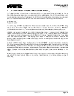
5.3.1.  Global Control 

Enable Pop Suppression:

  This section allows the user to enable or disable the Pop suppression 

globally. Pop suppression is used for reducing the pop/click sound when the audio switch happens in 
upstream path. 
 

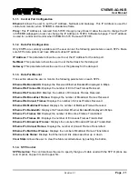
5.3.2.  Link Monitoring 

For each of 10 TDM inputs, the user can view the following parameters. 
 

TDM Source Detected: 

Displays the status of the TDM Input Presence. 

TDM Source Identifier:

 Displays where the TDM input source comes from. 

MADI Source Detected:

 Displays the status of the MADI Input Presence. 


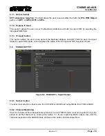
5.3.3.  Channel Monitoring 

User can monitor all 512 channel presence in each TDM Inputs and MADI Inputs. User can expand to 
view the status of all 512 channels by clicking this button “

+

”. If MADI Input is connected, first 64 audio 

channels responds to the MADI signals and rest of the audio channels shows red. 
 

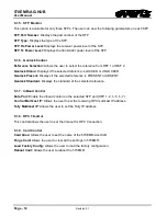
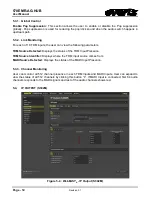
5.4. 

IP OUTPUT (S302M) 


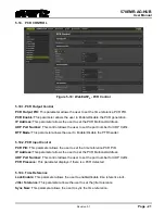
Figure 


5-4 : WebEASY

® 

- IP Output (S302M) 

Summary of Contents for 570EMR-AG-HUB

Page 1: ...he 570EMR AG HUB product Evertz Microsystems expressly prohibits the use of this guide for any purpose other than the operation of the contained in this reference guide consists of information that is the property of Evertz Microsystems and is intended solely for the use of purchasers of the 570EMR AG HUB product Due to on going research and development features and specifications in this manual a...

Page 2: ...This page left intentionally blank ...

Page 3: ...ird grounding prong The wide blade or the third prong is provided for your safety If the provided plug does not fit into your outlet consult an electrician for replacement of the obsolete outlet Protect the power cord from being walked on or pinched particularly at plugs convenience receptacles and the point where they exit from the apparatus Only use attachments accessories specified by the manuf...

Page 4: ... Class A digital device pursuant to Part 15 of the FCC Rules These limits are designed to provide reasonable protection against harmful interference when the equipment is operated in a commercial environment This equipment generates uses and can radiate radio frequency energy and if not installed and used in accordance with the instruction manual may cause harmful interference to radio communicati...

Page 5: ...ROUGH WEBEASY 9 5 1 SYSTEM 10 5 1 1 Control Port Configuration 11 5 1 2 Data Port Configuration 11 5 1 3 Data Port Monitor 11 5 1 4 SFP Control 11 5 1 5 SFP Monitor 12 5 1 6 Genlock Control 12 5 1 7 InBand Control 12 5 1 8 RPC TimeOut 12 5 1 9 Card Control 12 5 2 PRODUCT FEATURES 13 5 3 SIGNAL INPUT 13 5 3 1 Global Control 14 5 3 2 Link Monitoring 14 5 3 3 Channel Monitoring 14 5 4 IP OUTPUT S302M...

Page 6: ... 10 PCR CONTROL 21 5 10 1 PCR Output Control 21 5 10 2 PCR Input Control 21 5 10 3 Time Reference 21 5 11 PTP CONTROL 22 5 12 NOTIFY 22 6 APPENDIX 23 Figures Figure 3 1 570EMR Front left and Rear Plate right 5 Figure 3 2 570EMR Main TDM MADI Inputs Outputs 6 Figure 5 1 WebEASY System 10 Figure 5 2 WebEASY Product Features 13 Figure 5 3 WebEASY Signal Input 13 Figure 5 4 WebEASY IP Output S302M 14 ...

Page 7: ...570EMR AG HUB User Manual TABLE OF CONTENTS Revision 0 1 Page iii ...

Page 8: ...y offered by Evertz in relation to this product is the Evertz standard limited warranty stated in the sales contract or order confirmation form Although every attempt has been made to accurately describe the features installation and operation of this product in this reference guide no warranty is granted nor liability assumed in relation to any errors or omissions unless specifically undertaken i...

Page 9: ...570EMR AG HUB User Manual TABLE OF CONTENTS Revision 0 1 Page v This page left intentionally blank ...

Page 10: ......

Page 11: ...nnels and must have one dedicated Multicast Address associated with it Each TDM input must have 128 dedicated multicast addresses of Transport Streams The 570EMR AG HUB rear panel occupies 2 slots in 570 Frame and has 20 x DIN 1 0 2 3 connectors 1 1 FEATURES BENEFITS 10 TDM MADI Inputs 10 TDM MADI Outputs 8 x SFP 10GE trunk interfaces Supports TDM V2 Supports pop Suppression Supports PCR and PTP S...

Page 12: ...r Redundant Inband Control RTP Control Option to globally Enable or Disable the RTP header for the incoming TS s Incoming TS s doesn t have RTP header and AG card is set Enable for RTP There will be no audio in TDM Outputs Incoming TS s has RTP header and AG card is set Enable for RTP There will be audio in TDM Outputs Incoming TS s doesn t have RTP header and AG card is set Disable for RTP There ...

Page 13: ...mber of TDM MADI Outputs 10 x DIN Connector DIN 1 0 2 3 Impedance 75 Ω terminating 2 2 ETHERNET INTERFACE Number of SFP Ports 8 x 10GE SFP Rest of them are for future development 2 3 ELECTRICAL Voltage 12VDC Power Consumption 70W 2 4 FRAMES Frame and Slot Occupancy 570 Frame with 2 slot occupancy 570 Standalone Frame ...

Page 14: ...570EMR AG HUB User Manual Page 4 Revision 0 1 This page left intentionally blank ...

Page 15: ...e front plate of 570EMR AG HUB is equipped with 12 10GE SFP ports capable of passing receiving 10GE of data per port Only 8 x 10GE SFP ports are available to be used 3 1 2 Rear Plate The rear plate of 570EMR AG HUB is equipped with 20 DIN connectors The 1 10 DIN connectors are used for TDM MADI Inputs and 11 20 DIN connectors are used for TDM MADI Outputs ...

Page 16: ...570EMR AG HUB User Manual Page 6 Revision 0 1 3 1 3 Rear Plate Mapping Figure 3 2 570EMR Main TDM MADI Inputs Outputs ...

Page 17: ... the rack the two slots and remove the blank panels Insert the rear panel into the back of the chassis and secure using the screws provided Now insert the 570EMR AG HUB card into the corresponding front slots ensuring the card lines up with the slot runners on the bottom and the top of the chassis Push the card firmly into the slot ensuring that when it mates with the rear card it has been firmly ...

Page 18: ...570EMR AG HUB User Manual Page 8 Revision 0 1 This page left intentionally blank ...

Page 19: ...Software tab from 570FC webpage and select the IP Configure Mode Static or DHCP Then select the Slot where you see the 570EMR in 570 Menu Page and Enable the Proxy Mode under the selected Slot then it will displays three fields to enter the IP Address Netmask and Gateway After configuring three fields Click Apply to save the settings and refresh the page to see the settings are saved Go back to 57...

Page 20: ...570EMR AG HUB User Manual Page 10 Revision 0 1 5 1 SYSTEM This tab provides the basic configurations Monitoring of IP address InBand Control Data Port Monitoring and Reference Figure 5 1 WebEASY System ...

Page 21: ...dwidth Displays the Received Ethernet Bandwidth displayed in Mbps Ethernet Rx Frames Ok Displays the number of Error Free Frames Received Ethernet Rx Frames Err Displays the number of Erroneous Frames Received Ethernet Rx Broadcast Frames Displays the number of Broadcast Frames Received Ethernet Rx Unicast Frames Displays the number of Unicast Frames Received Ethernet Rx MultiCast Frames Displays ...

Page 22: ...KED or UNLOCKED Genlock Present Displays if the selected reference is PRESENT or ABSENT Genlock Standard Displays the standard of the selected reference 5 1 7 InBand Control Data Port Enable the Inband control on the selected SFP port SFP 1 2 3 5 6 7 Control Multicast IP Allows the user to set the receiving RPC multicast IP address Tally Multicast IP Allows the user to set the Tally IP address 5 1...

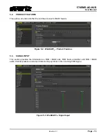
Page 23: ... the card has license for MADI feature Figure 5 2 WebEASY Product Features 5 3 SIGNAL INPUT This section provides the information on TDM MADI Link TDM Source Identifier and TDM MADI audio channel presence and also it detects the pop clicks in the incoming TDM signal Figure 5 3 WebEASY Signal Input ...

Page 24: ...ers TDM Source Detected Displays the status of the TDM Input Presence TDM Source Identifier Displays where the TDM input source comes from MADI Source Detected Displays the status of the MADI Input Presence 5 3 3 Channel Monitoring User can monitor all 512 channel presence in each TDM Inputs and MADI Inputs User can expand to view the status of all 512 channels by clicking this button If MADI Inpu...

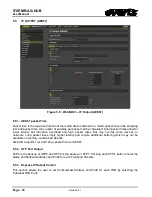
Page 25: ...Address and UDP Port for each Transport Stream in each TDM Inputs Also it displays the status of the IP Output NOTE All the multicast addresses are set automatically via SDVN Manual setup is for exceptional cases 5 4 4 IP Output Advanced Control IP Output Source IP Address This field allows the user to set the Source IP Address of each TDM Input IP Output Source UDP Port This field allows the user...

Page 26: ...high packet rates that may overtax some devices or networks Long packet times imply higher latency and require additional buffering which may not be available on memory constrained devices AG HUB supports 1ms and 125µs packet time for AES67 5 5 2 SFP Port Output SFP6 is the backup of SFP5 and SFP8 is the backup of SFP7 Clicking each SFP s button shows the status and Multicast address and Port for ...

Page 27: ...y via SDVN Manual setup is for exceptional cases 5 5 5 IP Output Advanced Control IP Output Source IP Address Allows the user to set the Source IP Address of each TDM Input IP Output Source UDP Port Allows the user to set the Source UDP Port of each TDM Input IP Output Type Of Service Allows the user to set the ToS if the network doesn t support ToS use zero as default IP Output Time To Live Allow...

Page 28: ...s 5 6 3 IP Input Control This section allows the user to see and set the Multicast Address and UDP Port for the each Transport Stream in each TDM Inputs Also it displays the status of the IP Input and RTP Sequence Errors 5 6 4 RTP Control This mode is used for filtering the RTP header and it is applied for entire TDM Outputs For instance if the incoming IP packet doesn t have RTP Header and does w...

Page 29: ...et the Multicast Address and UDP Port for each Transport Stream in each TDM Inputs Also it displays the status of the IP Input and RTP Sequence Errors 5 8 SIGNAL OUTPUT Figure 5 8 WebEASY Signal Output 5 8 1 Output Control The user must select the input source from ST302M or AES67 and output Mode from TDM or MADI 5 8 2 Channel Monitoring User can monitor all 512 channel carrier presence in each TD...

Page 30: ...re stamping the PTS value on its output audio 570IPG does not add any offset so this can should be 0 in your case But some compressed JPG MPG devices add Codec Latency value and that offset should be told to AG HUB Otherwise AG HUB will get audio packets that are too far in the future and it won t know how to store them In MANUAL mode User only needs to specify how much input to output delay you w...

Page 31: ... RTP Mode This parameter allows the user to Enable Disable the PTR header 5 10 2 PCR Input Control PCR PID This parameter allows the user to set the time reference PCR PID IP Address This parameter allows the user to set the PCR Multicast Address UDP Port Number This control allows the user to set the port number for UDP traffic PCR Presence This parameter displays if there is a PCR detected 5 10 ...

Page 32: ...stribute time and timebase to every device in the system Senders mark each packet of video audio or ANC with an RTP Timestamp that indicates the sampling time or equivalent Receivers compare these timestamps in order to properly align the different essence parts to each other 5 12 NOTIFY Figure 5 12 WebEASY Notify ...

Page 33: ...Reference PCR Synchronization of the Receiver System Time Clock STC with the Transmitter STC depends on transmitting PCRs through a constant delay portion of the system Thus PCRs are inserted following the encoder buffer and extracted before the receiver buffer PCRs are inserted with a maximum interval of 100ms Packet Time AES67 Packet time is the real time duration of the media data contained in ...

Page 34: ...570EMR AG HUB User Manual Page 24 Revision 0 1 End of Document ...

Reviews: