3405 Frame Manual
3405FRS-BNC Fiber Optic SFP Frame
Page - 10
Revision 1.1
4.1.2. Optical Fiber Handling and Care
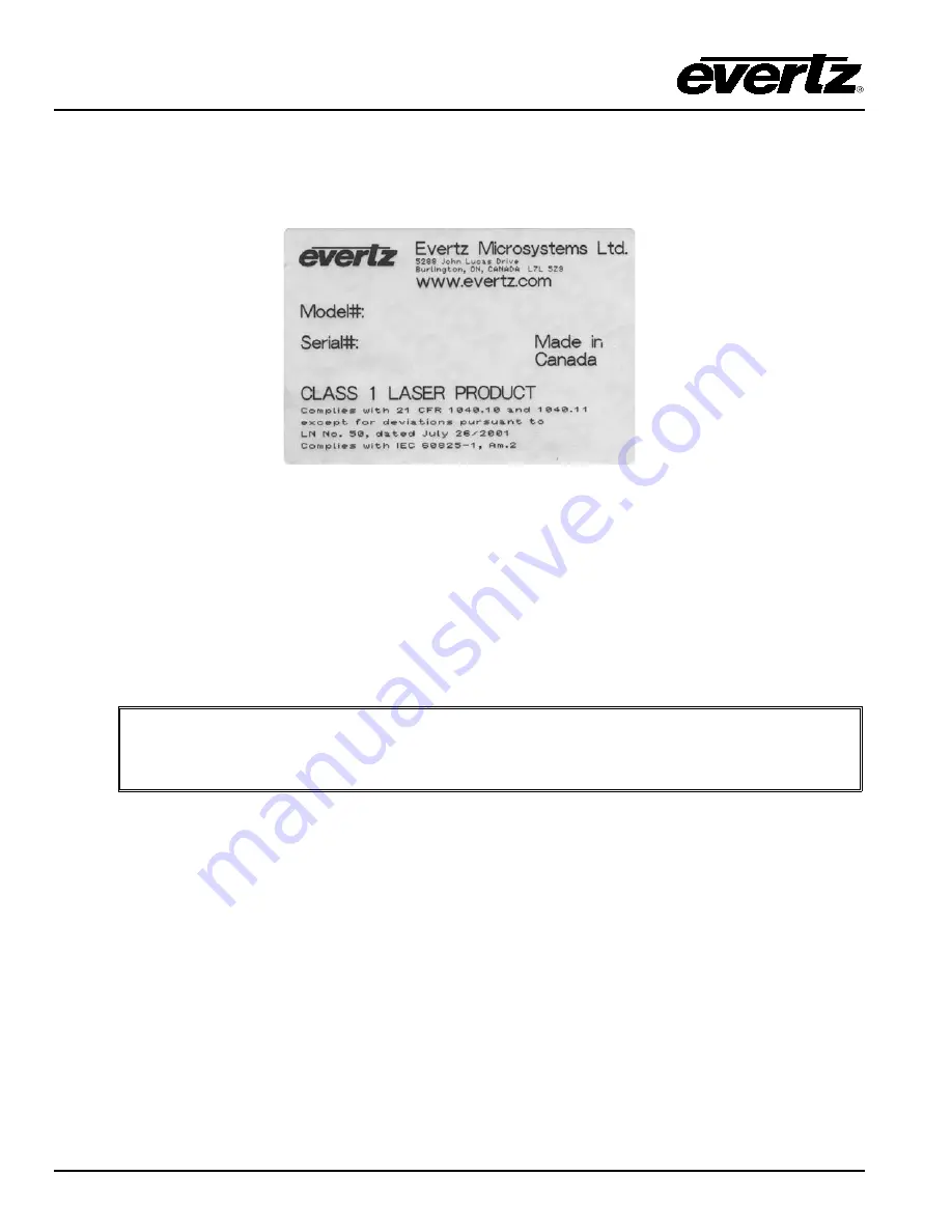
The SFP fiber modules are equipped with a class 1 laser and emit invisible radiation. Avoid exposure to
the laser emitter and do not stare directly into unconnected SFP emitter ports or fiber ends that are
connected to SFP ports.
•
It is recommended that trained and qualified personnel install, replace or handle this equipment.
•
Ensure ESD precautions are followed during SFP install.
•
Store SFP modules in static bags and wear an ESD strap when handling the optical modules.
SFP modules are also dust sensitive.
•
To prevent dust from entering the apertures of an SFP module, keep plugs inserted into the optical
bores.
•
Do not repeatedly remove and insert SFP modules more often than necessary. Repeated
removals and insertions of an SFP module can shorten its life.
4.1.3. Installing an SFP Module
Note: In most cases, SFP modules will come from the factory preinstalled into its
respective slot. The following steps outline the procedure for replacing or installing a
new SFP module.
1. Remove the SFP module from its protective packaging. You can identify if your particular SFP
module is a duplex transmitter or duplex receiver. Observe the top of the SFP module. The part
number is located on the top of the SFP module. A 3405T13-2 or 3405Txx-2 part number denotes
a duplex transmitter module (output) and a 3405R-2 and 3405R-2R denotes a duplex receiver
module (input). A 3405T13-R part number denotes a reclocking simplex transmitter module
(output) and a 3405OO13-DA4 denotes a reclocking simplex receiver module (input).
2. Hold the sides of the SFP module between your thumb and forefinger, position the alignment
grooves on the sides of the SFP with the corresponding guides in the SFP slot on your module.
3. Slide the SFP gently but firmly into the SFP slot. You should hear a click when the clips on either
side of the SFP snap into place, locking the SFP in the port receptacle.


