


22
General TIG Arc Starting Steps
1. Turn unit on, allow time for power up cycle to complete its start up process.
2. Select either TIG with TIG /CUT/Stick selector switch.
3. Plug in Torch and select panel mode with the selector switch
OR
plug in foot pedal and select Pedal.
4. If using the torch switch, Post Flow time by rotating the knob to increase/decrease.
5. Adjust amps with amp control knob.
6. Start arc as depicted above.
7. If using panel mode, continue to hold the torch switch until you are ready to stop welding. Release the switch. The Arc will then cease.
If using pedal raise foot fully off the pedal and arc will stop automatically.
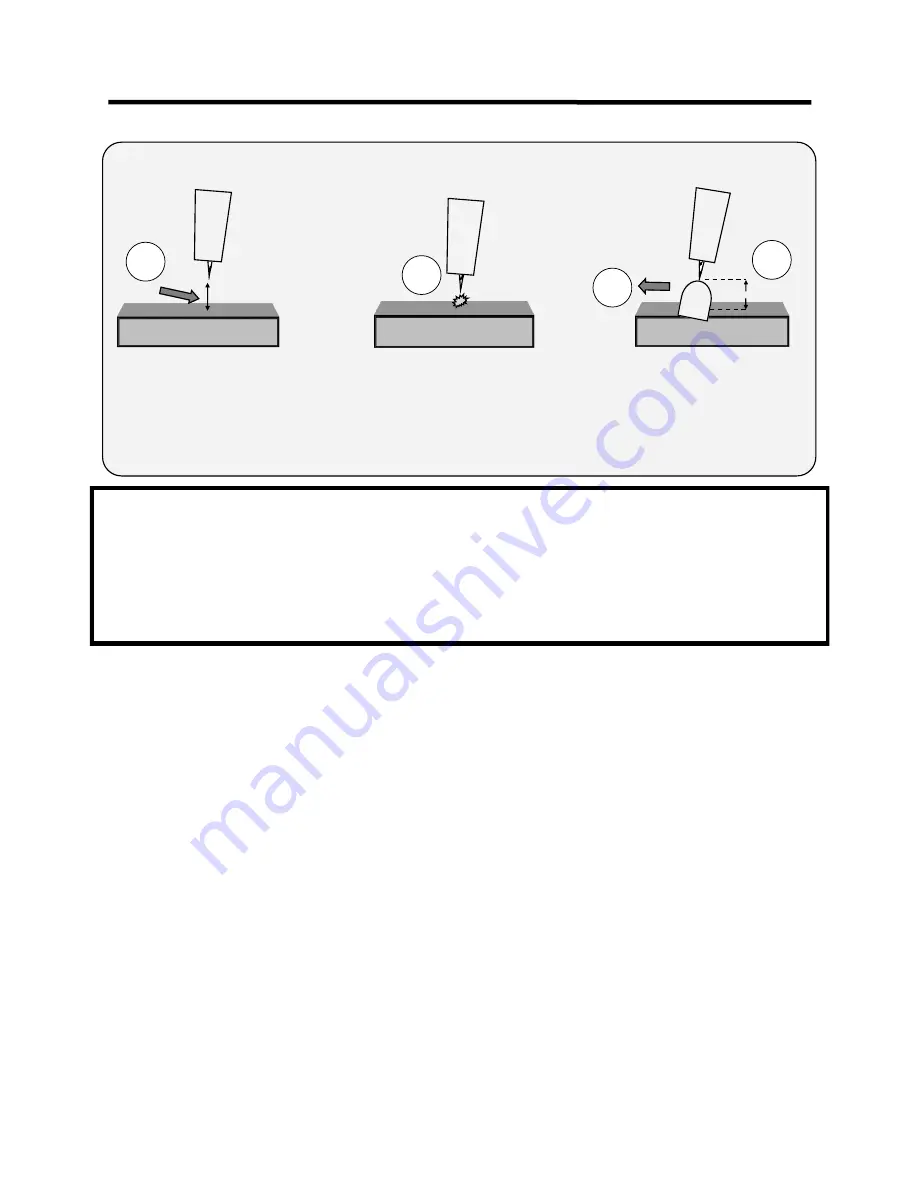
HIGH FREQUENCY START TIG OPERATION
<1/8
<1/8”
1
2
3
1. Position the point of the sharpened tungsten about
1/8”
or less above the metal.
2. Press the torch trigger or press the foot pedal to initiate the arc. The HF arc will be initiated. It may appear briefly as a blue spark.
3. An arc should form, almost immediately after the pre
-
flow cycle is completed. HF arc initiation will be delayed by the amount of pre
-
flow
time used. If arc does not start after the pre
-
flow interval, and the HF is creating a spark, then check the work clamp contact with the work
piece. Move the tungsten closer to the work. Repeat steps 1 and 2.
4. Leave
1/8”
or less gap between the tungsten tip and the metal and proceed with welding, leaving the torch inclined at a 15° angle.
4
Basic theory and function
Section 3
Summary of Contents for superultra series
Page 34: ...34...


