Everlast POWERARC 300ST Operator'S Manual Download Page 19

19


GENERAL SETUP AND OPERATION 

Section 2 

Note: This method takes some practice to master to initiate the arc on the first try.  However, an arc can usually be struck fairly easily by the beginner, though 

it may take 2 or 3 times to get one to initiate properly.  After it is mastered, arc striking can be done with a light, seamless motion on the first try.   Be sure to 

protect the cup from damage when not in use.  The Alumina  TIG cups are fragile and can easily crack if dropped or tapped on the surface. 
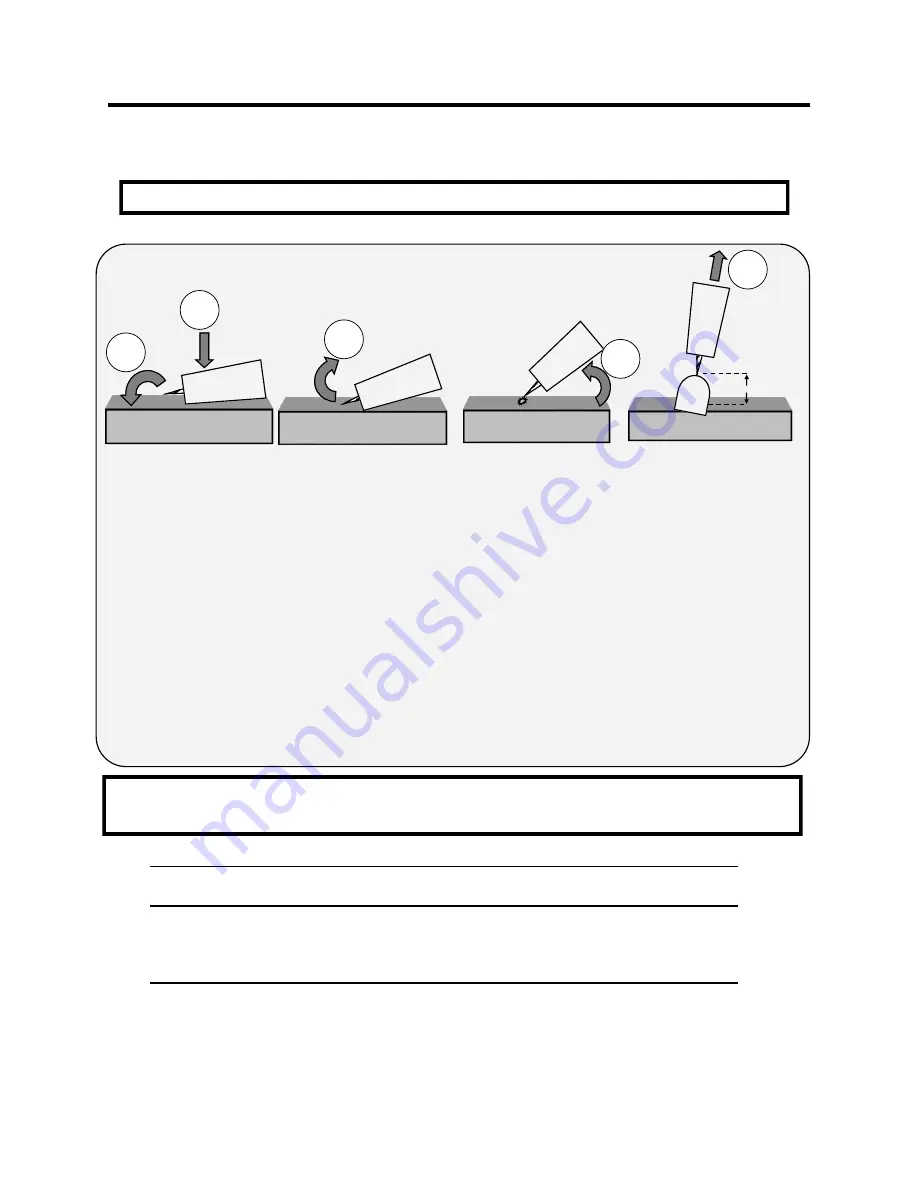
 

5.     Leave 

1/8” 

or less gap between the tungsten tip and the metal.


1

.     Position the edge of the ceramic cup on the metal.  Do not touch the tungsten to the metal until ready.  The tip is always live.


2.     Quickly rotate the cup so that the tungsten comes in brief contact  (< .2 seconds) with the metal.


3.     After contact with the metal, quickly rock the torch back so that the tungsten breaks contact with the metal.


<1/8”


Note: 


A Lift start should be done with a nearly seamless motion.  Use a light touch and a quick motion for best results.


1


2


3


4


5


LIFT START TIG OPERATION


4.     An arc should form.  As the arc grows, raise the cup up off the metal and slowly rotate the torch into welding position. 


6.     Poor starts and welding of the tungsten to the surface can be a result of a rapid 

double tap

” 

or quick bounce off the surface 

of the metal and back down.  This inadvertently signals the inverter to put out full power until the continuity or arc is broken.   

If this occurs, fully break the arc by releasing the switch or pedal. Re

-

sharpen the point if necessary, then allow the point to 

stop glowing before attempting the start again.  Do not scratch start in Lift TIG mode, or the tungsten may stick fast.  Per-

forming a scratch start instead of a lift start can also trigger this as the tungsten 

skips

” 

along the surface.


METAL THICKNESS 

(STEEL)


WELDING AMPS 

(A)


TUNGSTEN DIA.


Ar FLOW RATE


1

-

3 mm/.040

-

3/32”


30

-

80 


1.5

-

2 mm/ 

1/16”

-

3/32”


8

-

15 CFH /4

-

7 lpm


3

-

4 mm/ 

3/32”

-

1/8”


50

-

120


2

-

3 mm/ 

3/32”

-

1/8”


15

-

25 CFH/ 7

-

14 lpm


>4mm/ 

>1/8”


120

-

200+


1/8”


15

-

25 CFH/7

-

14 lpm


Note: These ranges are approximate, and not absolute.  There is a range of overlapping capability with each tungsten size, metal 

thickness and amp settings.   Experience will eventually dictate the best range and choice of Tungsten size, filler size etc.  As a 

general rule, select a filler metal that is no more than 

1/32” 

larger or smaller than the Tungsten diameter.  Do not use 

pure

” 

(green)  Tungsten in an inverter.  Use only  Lanthanated, Thoriated,  or Ceriated Tungsten.


Summary of Contents for POWERARC 300ST

Page 1: ...Setup and General Use Guide Rev 3 1 001229 16 Analog DC Stick DC TIG IGBT Inverter Welder CC SMAW IGBT 1 3 PHASE DC everlastwelders com 1 877 755 9353 329 Littlefield Ave South San Francisco CA 94080...

Page 2: ...uct in this manual are subject to change without notice or up date of this manual This manual is intended to be a general guide and not intended to be exhaustive in its content regarding safety weldin...

Page 3: ...nce technical support available through the main company headquarters available in your country For best service call the appropriate support line and follow up with an email particularly if off hours...

Page 4: ...orums index php Main toll free number 1 877 755 WELD 9353 9am 5pm PST M F 11am 4pm PST Sat FAX 1 650 588 8817 Everlast Canada Everlast consumer satisfaction email sales everlastwelders ca Everlast Web...

Page 5: ...unit Do not operate the unit until you have read this manual and you are thoroughly familiar with the safe operation of the unit If you feel you need more information please contact Everlast Support...

Page 6: ...equip ment If no protection is available exclude them from the work area Even brief expo sure to the rays from the welding arc can damage unprotected eyes Always wear hearing protection because weldi...

Page 7: ...y burning of the eyes nose or throat are signs that you need to increase ventilation Stop immediately and relocate work if necessary until adequate ventilation is ob tained Stop work completely and se...

Page 8: ...ion Keep all combustible materials including rags and spare clothing away from area Keep all flammable fuels and liquids stored separately from work area Visually inspect work area when job is complet...

Page 9: ...aluminum or magnesium Need longer welding cables or an extension cord The welding cables are held into the DINSE style connectors by set screws located under the connector cover and can be accessed by...

Page 10: ...The hot start can blow through the metal if the setting is too high for the given thickness of the metal On thin metals use a lightly penetrating rod such as an E6013 and a low hot start setting Arc...

Page 11: ...g Contact Everlast for an optional TIG package if desired or source one local ly at a nearby welding supply store 2 3 Handling and general maintenance Duty Cycle and Overcurrent Be careful to observe...

Page 12: ...e of the two negative ports Most electrodes require reverse polarity To maintain reverse polarity also known as positive polarity or DCEP the work clamp should be engaged in one of the two negative po...

Page 13: ...t is grounded by the main ground wire to the chassis an additional bonded ground may be necessary in some locations to comply with code Consult a locally licensed electrician concern ing the any requi...

Page 14: ...AN AND LOCAL CODES BEFORE MODIFYING EXISTING CIRCUITS OR IN STALLING THE WELDER See page 20 for further details and explanation GAS INLET 1 220 V OR 3 220v IMPORTANT EVERLAST IS NOT RESPONSIBLE FOR DA...

Page 15: ...NERAL SETUP AND OPERATION Section 2 6010 TORCH WORK 6010 NOTE Also suitable for use with E6011 and other electrodes with cellulose based flux such as E7010 PowerARC 300ST STICK E6010 WELDING CONFIGURA...

Page 16: ...TE Use this configuration with most standard electrodes except ones with cellulose flux such as E6010 6011 PowerARC 300ST STANDARD WELDING CONFIGURATION IMPORTANT Most electrodes require DCEP Always c...

Page 17: ...st flow A regula tor is still needed to regulate max flow To connect Everlast torches some adaptation or modification of the torch gas line will be needed as is the case with most gas valve torches to...

Page 18: ...electrode diameter selection chart below to determine the ap proximate range of amps suitable for the rod size selected Consult the welding electrode manufac turer s recommendation for proper amperage...

Page 19: ...rotate the torch into welding position 6 Poor starts and welding of the tungsten to the surface can be a result of a rapid double tap or quick bounce off the surface of the metal and back down This i...

Page 20: ...od sticking Wet welding rods Too low of amperage Too high of amperage Use fresh rods Adjust amps Wrong polarity Hot start Arc force too low Welding rod is rapidly consumed Too small of welding rod Too...

Page 21: ...Tong style Stick electrode holder 10ft cable with DINSE 50 style connector 1 Steel work clamp 10ft cable with DINSE 50 style connector 1 PowerARC 300ST DC Stick Inverter welder 1 Manual NOTE Kit cont...

Page 22: ...s used for a dryer or range connection do not match up to the standard wire colors used in wiring a welder In three phase 4 wires are used with 3 hot wires again out of phase with each other are used...

Reviews: