


19
INSTALL THE WIRE AND FEED THE GUN.
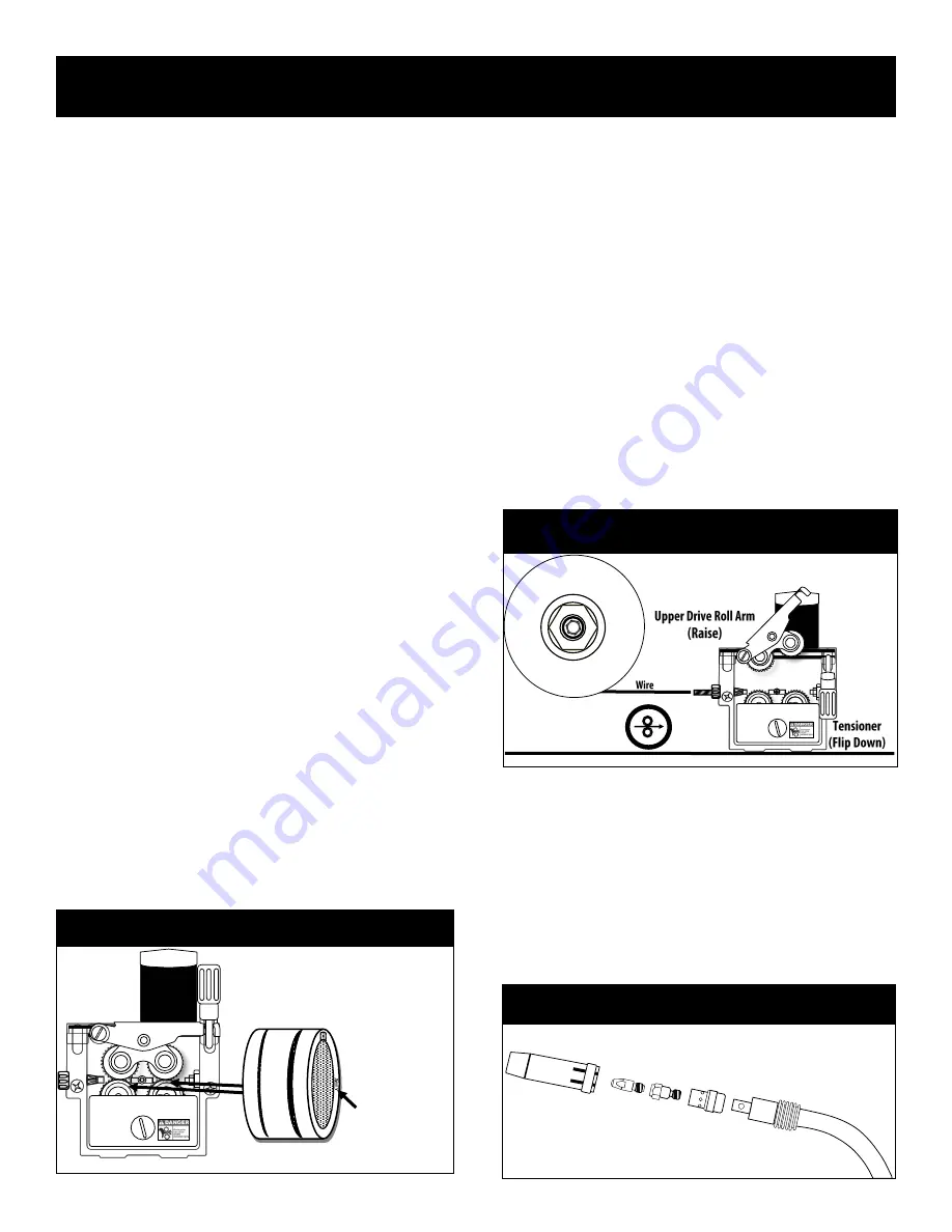
Once the wire spool has been installed, flip the tensioner lever down
and raise the top drive rolls to the upper position. See the illustration
below. Gently guide the wire from the spool over through the wire
feeder and into the front section of the gun at least 6 inches. Make
sure the wire lays neatly in the grooves of both drive rolls. Hold it
with your finger if necessary as you lower the upper drive roll arm
down and raise the tensioning lever into position with your other
hand. After the tensioner is raised back to the vertical position, con-
firm the wire is still in both grooves and is not riding up on the shoul-
ders of either drive roll. Next, turn the welder on and set to a desired
MIG or Flux
-
Cored mode. Remove the gas nozzle by pulling it with a
slight twist. Unscrew the contact tip as shown in the illustration be-
low. Use a wrench to hold the contact tip holder so it won
’
t unscrew
when the contact tip is removed. Hold the gun cable and gun straight
as possible. Press and hold the wire jog button. The wire should
slowly begin to feed through the gun cable and eventually through the
gun. As the wire exits the gun, allow 3 extra inches of wire to be fed
out past the diffusor. Release the wire job button. Re
-
install the con-
tact tip over the wire and screw it in clockwise until it is snug. Do not
overtighten. Install the gas nozzle.
Hint: The wire on the spool is usually bent and threaded through a
small hole in the side of the spool to lock it in place and prevent de
-
spooling of the wire. Keep one hand on the wire spool to prevent
despooling and cut the wire loose with a pair of wire cutters. Trim the
wire to make sure the end of the wire is straight and able to be
Setup Guide
Getting Started
CHECK AND CHANGE YOUR DRIVE ROLL.
The unit comes with a pair of
.035”
and
.045”
drive rolls installed.
Remember, if you change wire size or type, you will need to either flip
both of the lower drive rolls over for the opposing size or completely
change both of the drive rolls out with the ones of correct size and
type found in the consumable bag. When not in use, keep these
“
spares
”
put up where moisture and dust cannot get to them. They will
rust if not used and stored properly.
The top drive rolls are actually idler rolls used to hold tension and
keep the wire in the groove. These are not changeable. Only the bot-
tom drive rolls needs to be changed. Each of the bottom drive rolls
have two small grooves that are sized for
.030”
(.8mm)
and
.035”
(.9mm) solid wire. Additional sizes and types of drive rolls
are available as options. The standard installed drive roll is meant to
feed hard (solid) steel wire. The groove on this drive roll has a
“
V
”
shape designed for the solid wire. A Flux
-
Cored drive roll has a ser-
rated edge to the groove, which grips the softer, cored wire. Viewing a
flux
-
core drive roll from the top, you will see a
“
zipper
”
like pattern.
This should never be used to feed hard steel, stainless or aluminum
wire. This will result in damage to the wire, metal flaking and possible
plugging of the MIG gun liner. To determine the exact size of wire and
type you have, look at the side of the drive roll. The size of the drive
roll groove is stamped on the side of the drive roll closest to the corre-
sponding groove. The type of the drive roll will also be stamped with a
V if it is for solid, hard wire. If it is stamped with an
“
U
”,
this is a spe-
cial drive roll for feeding aluminum wire. Aluminum wire is best fed
with a spool gun.
The drive rolls are held in place by a screw. Use a flat head screw
driver to gently remove the screws to expose and change the drive roll.
The drive rolls are mounted on a bushing. To prevent the bushing
from being removed along with the drive roll, use the index finger of
one of your hands to hold the bushing while the other hand removes
the drive roll. When removing make sure that the square locating key
is not dismounted. If the key falls out of the keyway, replace it before
replacing the drive roll. When the drive roll is reinstalled, just lightly
snug the screws with the screw driver. Do not over tighten.
Drive Roll Size and Location Info
.6mm
=.023”/.025”
.8mm=
.030”
.9mm=
.035”
1.2mm=
.045”
1.6mm=
.062”
Size/Type Stamping.
(The size is stamped on
same side as the corre-
sponding groove.)
Installing the MIG Wire
How Do I Disassemble the MIG Gun?
M8
Contact Tip
Diffusor
Gas Nozzle
Contact Tip
Holder
Gun Neck
Drive Rolls X 2


