7
Controls and inspections
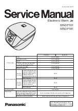
Before starting the appliance, check the oil level
through the sight glass located on the
motor/pump.
(Fig. 5.1). In order to access the pump, unscrew
the back panel of the appliance and remove it.
(Fig. 5.1
.) Pump oil level indicators
After checking the oil level and ensuring it is level
with the maximum oil level indicator, reinstall the
back panel and secure it with the screws you
removed. Connect the plug to the proper outlet.
If it is not the correct outlet, the outlet must be
replaced with the correct one by a qualified
electrician, as well as ensuring the fuse or
breaker is the correct current capacity for the
draw of the appliance.
Do not use adapters,
multiple outlets and/or extension cords.
Do not plug in multiple appliances on the same
outlet that may exceed current capacity of the
outlet.
This appliance must be grounded properly.
If the ground prong is broken, do not use
the appliance until it has been repaired or
serious injury or death may occur.
CHAPTER 6
USING THE VACUUM SEALER
Vacuum packaging
1. Plug in the grounded plug to the correct
outlet.
2. First turn on the main power switch on the
front of the appliance. Next press the
ON/OFF button on the control and the LCD
display should light up.
3. Set the vacuum time (or percentage)
required, the sealing time and the gas
injection time (if the appliance is equipped
with this option.).
4. Position the bag (or bags) with product in
the chamber, the polyethylene shelves can
be used inside the vacuum chamber to level
the product with the sealing bar and position
the bag opening flat on the sealing bar.
The
polyethylene shelves can be removed
depending on necessity. (Fig. 6.1).
5. Lower the clear bell-lid and press firmly on it
until it remains closed, thus permitting the
sealing cycle to begin.
6. The different cycle phases are automatic and
after a pre-set amount of time the clear bell-
lid opens thus enabling the product to be
removed and subsequent cycles to begin.
(Fig. 6.1)
Correct bag placement in chamber
Vacuum-packaging with inert gas
injection OPTIONAL (ref. table 1)
1. Set the sealing cycle with inert gas injection
on the control panel by pre-selecting the
relative time.
2. Connect the hose coming from the gas
cylinder to the hose connection positioned
on the side/rear of the vacuum sealing
appliance by means of the relevant clamp,
then set the gas cylinder gauge at a
pressure value of 1 ATA.
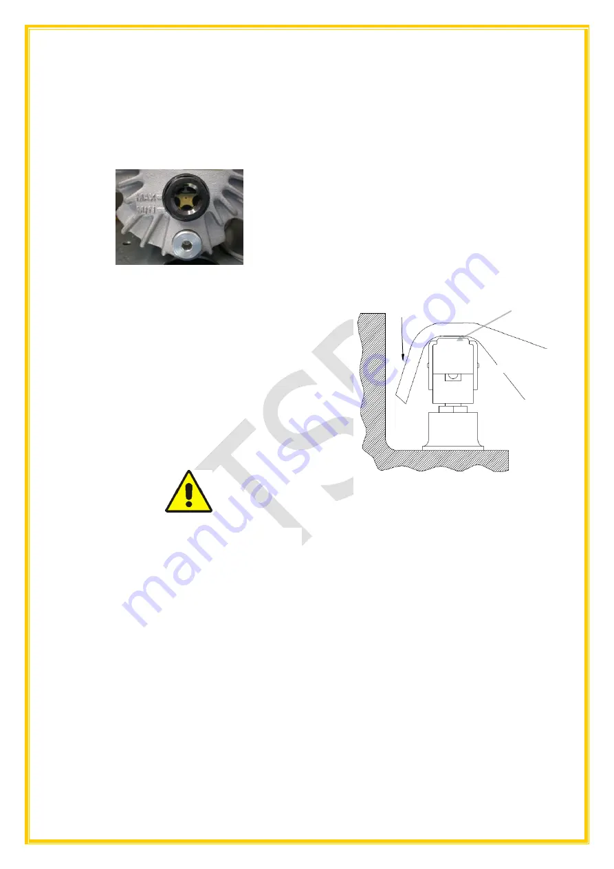
3.
Position the bag containing the product
inside the vacuum chamber, fitting the gas
distribution nozzle inside the bag
opening
(Fig. 6.2); make sure that there are no folds
obstructing the gas flow.
Open end of bag
Sealing bag
Cross Section of Chamber
Sealing
Bar
Summary of Contents for PrepRite PVS27-6-1
Page 17: ...17 CHAPTER 11...
Page 18: ...18 EXPLODED VIEWS AND PART...
Page 19: ...19 LISTS...
Page 20: ...20...
Page 21: ...21...
Page 22: ...22...
Page 23: ...23...
Page 24: ...24 CHAPTER 12 WIRING DIAGRAMS PVS27 PVS32 PVS32G PVS42 PVS42BG PVS5225 PVS52G...
Page 25: ...25...
Page 26: ...26...