background image


EPTZ9200/9300 Series


16 

10.


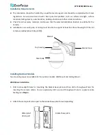
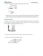
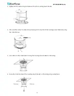
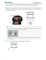
Slide the surface ring to the fillister and slightly turn it until it is firmly fixed. 


Note:

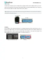
 When you turn on the power, the camera will enter self-inspection mode and run a self-testing 

program. Once this is complete, you will be able to operate it via EKB500 or other control device. 


5.


EKB500 Connection 

You can use EKB500 Keyboard to control the EPTZ cameras including the OSD menu setup or PTZ control. 
Follow the steps below to connect the EKB500 Keyboard to the EPTZ camera. 

1.


Connect EPTZ camera to EKB500 either using the RS-485 wire or through the connector box. 


Through the Connector Box 

RJ-45 Cable

Connector Box

Blue

Orange

Black

Red

White

Black

Yellow

Green

( RS-485 - )

( RS-485 + )

EPTZ Series 1

EPTZ Series 32

RS-485 +

RS-485 -

EKB500


Summary of Contents for EPTZ9200 Series

Page 1: ...EPTZ9200 9300 Series Speed Dome AHD 1080p Outdoor Indoor PTZ with True Day Night and WDR 20x 30x Optical Zoom Quick Installation Guide Copyright EverFocus Electronics Corp Release Date November 2015...

Page 2: ...rd pin connector and outer housing with bubble plus one tool packet in the package The detail accessories are listed below Standard 1 Camera Main Body x 1 2 Top Housing x1 3 Outer Housing with Bubble...

Page 3: ...wire carries RS 485 and the orange wire carries RS 485 Connect these wires to the EKB500 or other control device in order to control the PTZ camera I O Terminal Block The base board that is inside the...

Page 4: ...B 10 ALMIN3 Alarm Input 3 2 ALM_COM_B Alarm Output Common B 11 GND Ground 3 ALM_NC_B Alarm Output Normal Close B 12 ALMIN4 Alarm Input 4 4 ALM_NO_A Alarm Output Normal Open A 13 VIDEO 5 ALM_COM_A Ala...

Page 5: ...tdoors Corner mount adapter Used for fixing a wall mount bracket to a 90 wall corner indoors or outdoors Indoor ceiling pendant mount bracket adaptor Used for installing a speed dome against a ceiling...

Page 6: ...bags 1 On the Top Housing slightly press the black plastic socket backward and lift up the base board 2 Remove the desiccant bags from the top housing 3 Stick the supplied 3 new desiccant bags inside...

Page 7: ...en setting up the DIP Switch The new values will only take effect after restarting the camera DIP Switch Camera Main Body ID Address The ID address of the camera should be set to correspond properly w...

Page 8: ...tch Address Switch Address Switch Address Switch Address Switch Address Switch Address ON 1 2 3 4 5 6 7 8 Switch Address 65 ON 1 2 3 4 5 6 7 8 66 ON 1 2 3 4 5 6 7 8 67 ON 1 2 3 4 5 6 7 8 68 ON 1 2 3 4...

Page 9: ...5 6 7 8 191 Switch Address Switch Address Switch Address Switch Address Switch Address Switch Address ON 1 2 3 4 5 6 7 8 Switch Address 193 ON 1 2 3 4 5 6 7 8 194 ON 1 2 3 4 5 6 7 8 195 ON 1 2 3 4 5...

Page 10: ...the camera will enter a self test mode Baud Rate The fourth and fifth switches on the left are used to set the baud rate transmission speed Please refer to the sticker on the camera main body for sett...

Page 11: ...llations on a wall pole or ceiling must be able to support at least five times the weight of the full camera assembly about 16kg 35lb Installing Outdoor Models Two mounting types are available for the...

Page 12: ...all mount bracket 4 Connect the RS 485 video and power cables through the top hole of the base board If necessary connect the alarm cable as well using the bottom hole 5 Screw the bracket base to the...

Page 13: ...sing lines up with the red triangle on the outside of the main body Push the main body upward into the top housing until the orange catches on both sides click into position Top Housing Main Body Note...

Page 14: ...B500 or other control device Ceiling Mount Installation It is required to use the optional In ceiling Mount Bracket Recessed Mount Bracket and Surface Ring to attach the camera to the ceiling for supp...

Page 15: ...ace and then screw the camera s top housing on the top disk of the in ceiling mount bracket by using the 3 short screws Top Disk 5 Use a cable or other mechanism to hang the in ceiling mount bracket o...

Page 16: ...the outside of the main body Push the main body upward into the top housing until the orange catches on both sides click into position Top Housing Main Body Note 1 To release the main body press the...

Page 17: ...EKB500 or other control device 5 EKB500 Connection You can use EKB500 Keyboard to control the EPTZ cameras including the OSD menu setup or PTZ control Follow the steps below to connect the EKB500 Keyb...

Page 18: ...above connection you can start operating EPTZ camera with EKB500 Keyboard IRIS Focus F Zoom In N Out UP DOWN LEFT RIGHT Zoom IN Zoom OUT 1 Move the Joystick up down left right to shift the camera view...

Page 19: ...F Kuramochi Building II 2 2 3 Koto Bashi Sumida Ku Tokyo 130 0022 Japan TEL 81 3 5625 8188 FAX 81 3 5625 8189 www everfocus co jp info everfocus co jp Your EverFocus product is designed and manufactur...

Reviews: