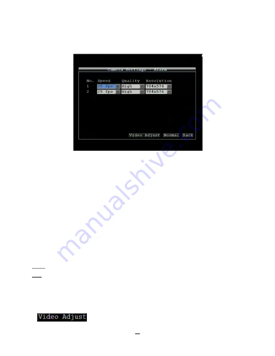
EverFocus EMV200 User Manual Download Page 31


24 

4.2


CAMERA SETTING 

Figure 4-3 is a screenshot of the 

CAMERA SETTING MENU

. This menu is used to configure individual camera 

settings. 


Figure 4-3 Camera Settings-Normal 


4.2.1  Normal 

No.:

 Camera number. 

Speed:

 Frame rate in frames (images) per second (FPS) for  continuous recording. The speed is limited by the 

maximum total recording capacity of the DVR as allocated across all the installed cameras, with an upper limit of 
30 FPS (NTSC – 25 PAL) per individual camera (real time recording). The DVR is capable of recording 480 CIF 
(352x240)  sized  frames  per  second  (NTSC;  400  PAL);  each  704x240  image  (2  CIF)  per  second  requires 
allocation of two of those CIF frames from the overall capacity of 480 CIF frames, and each 704x480 image (D1 or 
4  CIF)  per  second  requires  allocation  of  four  of  the  CIF  frames  from  the  overall  capacity.    Thus  the  DVR  can 
record a combination of CIF, 2 CIF and 4 CIF images,  with different combinations of image size/resolution and 
different FPS rates on different cameras, so long as the total CIF equivalents allocated is not greater than 480 CIF 
per second.  Choices for possible record speeds are 30, 15, 10, 7.5, 5, 1 and 0 FPS. 

Quality:

  Select  an  image  quality  for  recording.  There  are  five  different  qualities  available:  Superior,  High, 

Standard, Basic and Low.  A higher image quality uses more HDD space.  

Resolution:

 Select recording resolution based on video format. 

NTSC: 704x480 / 704x240 / 352x240 

PAL: 704x576 / 704x288 / 352x288 

Aud:

 Check this box to enable audio recording on the DVR. 

Ins:

  Check  the  box  to  enable  the  current  camera.  To  take  full  advantage  of  the  DVR’s  recording  abilities,  any 

unused cameras should have this option set to “disabled”. 


Click 

 button to enter Video Adjust menu. 

Summary of Contents for EMV200

Page 1: ...User Manual E EM MV V2 20 00 0 D DV VR R...

Page 2: ...ermission of the Everfocus Electronics Corporation Release Date Apr 2011 QuickTime is a registered trademark of the Apple Computer Inc Windows is a registered trademark of the Microsoft Corporation Li...

Page 3: ...and extension cords as this could cause fire or electric shock Power Cables Power cables and their connectors should be placed where they are not likely to be walked on crushed or pinched by items pla...

Page 4: ...f not installed and used in accordance with the instructions may cause harmful interference to radio communications However there is no guarantee that interference will not occur in a particular insta...

Page 5: ...B MOUSE INSTALLATION 11 1 13 NETWORK CONNECTION 12 1 13 1 Direct PC Connection through Crossover Network Cable 12 1 13 2 Network Connection through Patch Cable 13 1 14 FINAL INSTALL PROCESS 13 2 MOUSE...

Page 6: ...lay 41 4 6 3 Layout 42 4 6 4 Sequence 43 4 7 NETWORK SETTING 43 4 7 1 LAN Settings 44 4 7 2 Mobile Connection Settings 46 4 7 3 Email Settings 47 4 7 4 DDNS Settings 48 4 7 5 Alarm Server Settings 49...

Page 7: ...TYPICAL LINKSYS PORT FORWARDING 81 8 2 TYPICAL D LINK PORT FORWARDING 83 9 SD CARD READER 85 9 1 UNDERSTAND USER INTERFACES 85 9 2 BASIC OPERATIONS 86 9 2 1 Open File 86 9 2 2 Open SD 86 9 2 3 Playba...

Page 8: ...module and hand held IR remote control capability make this DVR the best choice for your 1 2 channel portable and mobile recording applications 1 1 FEATURES 2Channels of real time D1 video and audio...

Page 9: ...udio Inputs 2 line in vibration resistant locking Molex connectors Interface cables to RCA F provided Audio Outputs 1 line out vibration resistant locking Molex connectors Interface cables to RCA F pr...

Page 10: ...time source flexible DST settings Watchdog Function Reboots DVR automatically if required Networking RJ45 socket 10 100Mbps TCP IP DHCP PPPoE DDNS SMTP SSL POP3 HTTP NTP Interface RS 232 USB 2 0 Powe...

Page 11: ...connected amber LED flickers when data is being exchanged 6 Philips mounted Pin torx Use Philips screw for an easier mounting to prevent over tightening Use Pin torx for a safe installation to preven...

Page 12: ...audio input connection corresponding to the appropriate camera Video Output 1 Monitor for live and playback display and on screen display Audio Output 1 Connect to the line level input of an audio amp...

Page 13: ...GND Audio Video VIN1 VIN2 TV_OUT AUDIO_IN AUDIO_OUT GND GND GND GND GND Power In ING_IN GND GND DC12V 1 7 INSTALLATION OF EMV200 Step 1 Please put your EMV200 on the suitable location of vehicle Pleas...

Page 14: ...Locations Inside the Automobile Vehicle Truck Glove box inside or underneath Drive seat between seat and wall or Passenger seat underneath Users are suggested to use support for mounting option Show t...

Page 15: ...utomobile Vehicle Show the wiring on the wiring harness that connects to the electrical system Drive seat between seat and wall Trunk Users are suggested to use suspend for mounting option Glove box i...

Page 16: ...er supply connects from the Automotive adapter cigarette plug Monitor and cameras must be purchased separately Connect the Camera s Connect the power connector from the camera s harness into the CAMER...

Page 17: ...o output ATTENTION The direct connection of a non amplified microphone is not supported a microphone amplifier is required The audio output requires an amplifier to drive a speaker or headphones The i...

Page 18: ...osed contact in idle state in idle state 1 10 2 Alarm Output Relay The relay output provides either Normally Open or Normally Closed dry contacts Output relay in idle state 1 11 USB Mouse installation...

Page 19: ...ic types of connection 1 12 1 Direct PC Connection through Crossover Network Cable The point to point connection of DVR and PC requires a crossover crossed network cable This type of connection is ONL...

Page 20: ...rk switch or router Figure 1 4 Network Connection through Patch Cable Pinout of straight patch cable 1 13 FINAL INSTALL PROCESS Once you have completed the basic wiring connections you are ready to tu...

Page 21: ...ow to select a channel 1 In a view consisting of more than one channel users can select a channel by clicking once on the desired channel screen The selected screen will be highlighted by a white fram...

Page 22: ...e down arrow to see all selections then directly click on an option to select it Check box Click on the box to enable it checked or disable it unchecked Button Click the button to execute the function...

Page 23: ...ication To log in follow these steps 1 Right click on the screen to display the Main Menu 2 The following screen pops up Figure 3 1 Login page 3 Select the user name from the drop down list and input...

Page 24: ...een Configuration 2 Left click on the Playback icon to enter the Playback Menu A Playback Bar appear as shown below Playback Bar Name Description Layout TheEMV200 DVR has several display modes availab...

Page 25: ...out search function Archive Press to save a video clip to USB Please see 3 5 Archive for more details about archive function Zoom 2x and 4x electronic zoom Exit Exit from playback bar During playback...

Page 26: ...on to enter GPS search menu Click button to enter Event search menu Click button to go to live view 3 4 2 GPS Speed Search Click button to enter GPS search menu Figure 3 6 Search Menu GPS Search From...

Page 27: ...ongitude if border type is circle Radius If GPS border type is circle this option defines radius Select radius unit from Km and Mi Upper Left Lat Set Upper Left Latitude if border type is rectangle Up...

Page 28: ...g date and time Select which event type s to search for Choose from Alarm Video Loss or Power On Click on the button to select which cameras to include in the search Click on the button to start searc...

Page 29: ...click to enter Archive Menu Figure 3 10 Archive Menu Camera Select which cameras will be archived Choose Select All to select all the cameras Player Check the box to include the ePlayer program as par...

Page 30: ...DVR for your specific application 4 1 Configuration Menu 1 To bring up the Main Menu right click with the USB mouse to bring up the root menu Figure 4 1 Root Menu 2 Left click on the Configuration ico...

Page 31: ...quires allocation of four of the CIF frames from the overall capacity Thus the DVR can record a combination of CIF 2 CIF and 4 CIF images with different combinations of image size resolution and diffe...

Page 32: ...to be lost in the shadows or darker regions try increasing the Brightness If the image appears too saturated or if the colors appear overwhelmed by glare try decreasing the Brightness Contrast Adjust...

Page 33: ...15 CIF equivalent FPS still available to be assigned to one or more of the nine CIF resolution cameras If not all event conditions occur simultaneously greater resolution and or FPS increases are pos...

Page 34: ...n extend the recording time after ignition off Time Stamp Select if the time and date will display while recording Choose the location for the time display from Top Bottom or Off Vehicle ID Stamp Sele...

Page 35: ...hrough alarm and GPS setup Figure 4 8 Alarm GPS Alarm 4 4 1 Alarm Alarm Settings Figure 4 9 Alarm Alarm Settings Alarm Select the alarm input trigger connection number from 1 to 2 Enable Check box to...

Page 36: ...nds then continues for the set time duration Timeout Duration Time duration selectable from 1 to 150 seconds Pre alarm Record Check box to start copying recorded video to the hard disk from 5 seconds...

Page 37: ...If power is disconnected an alarm event will be triggered when power is restored Network Loss If connection to the local network is lost DVR will create a Network Loss event NOTE This function only ch...

Page 38: ...ets the alarm remotely Transparent Alarm output remains active until event ends Trans Timeout Alarm output continues until event ends then continues for the set time duration Timeout Duration Time dur...

Page 39: ...el of menu Power Loss Figure 4 16 Alarm Event Power Loss Email Notify Check box to enable email notification when power has been restored Email operation requires that valid email settings have been e...

Page 40: ...resses Enter key Transparent Alarm output remains active until event ends Trans Timeout Alarm output continues until event ends then lasts for the set time duration Timeout Duration The amount of time...

Page 41: ...e Output Type Output action when alarm is triggered Timeout Alarm output lasts for the set time duration Permanent Alarm will be continuously active until user presses Enter key Transparent Alarm outp...

Page 42: ...the event ends then continues for a set time duration Pre alarm Record Check box to start copying recorded video to the hard disk from 5 seconds before the video loss Pre alarm recording rate will fo...

Page 43: ...ver the desired speed display units must be selected Select GPS speed unit from KPH and MPH Selecting MPH converts the GPS signal to display speed in miles per hour GPS Speed Select whether to record...

Page 44: ...ends then lasts for the set time duration Timeout Duration The amount of time the buzzer sounds when GPS event occurs Duration selectable from 1 to 150 seconds Pre alarm Record Check box to start copy...

Page 45: ...is circle Center Longitude Set the latitude if border type is circle Radius If GPS border type is circle this option defines radius Select radius unit from Km and Mi Upper Left Latitude Set Upper Lef...

Page 46: ...to do the following NTP settings Update Interval The frequency that the system automatically updates the time via the NTP server Select Daily Weekly or Monthly NTP Server Displays the time server addr...

Page 47: ...ange to when daylight saving begins For most regions this will be one hour ahead of the Start Time End Date Set the end date for daylight saving time End Time hh mm Set the time when daylight saving t...

Page 48: ...d Maximum text length is 16 characters Camera 1 2 Input camera name for camera 1 2 by using the on screen keyboard Maximum text length is 16 characters 4 6 2 Monitor On Screen Display Click button to...

Page 49: ...play playback status Event Status Check the box to display event status SD Card Status Check the box to display SD card status GPS Status Check the box to display GPS status Network Loss Select Disabl...

Page 50: ...m 0 to 99 seconds Sequence repeats continuously from steps 1 through 20 until interrupted Click button to return to the previous level of menu 4 7 NETWORK SETTING Figure 4 30 is a screenshot of the NE...

Page 51: ...A static IP address must be set manually If DHCP or PPPoE is selected this value will be assigned automatically Subnet Mask This field shows the subnet mask for your network so the DVR will be recogn...

Page 52: ...etwork hardware and configuration this may be the IP address of your router gateway or it may be the actual IP address of the local DNS server The DNS server IP is required because your DNS server pro...

Page 53: ...when connecting the DVR to busy or heavily loaded networks or when accessing the DVR s over a WAN Click button to start LAN reconnection Click button to return to the previous level of menu 4 7 2 Mob...

Page 54: ...the SMTP server requires authentication user name password SSL Check the box if mail server needs communication to be encrypted by SSL User name Input the login user name if the SMTP server requires a...

Page 55: ...aracters particularly _ In the DVR s Network Menu above go to DDNS Choose everfocusddns com for the Server and put in your chosen name verified available and without special characters for DVR Name ho...

Page 56: ...dns account User name User name of the dyndns account Password Password of the dyndns account Note For more details on DDNS setup please see Chapter 7 Everfocus DDNS Setup Click button to return to th...

Page 57: ...of menu 4 7 6 Meta Server Settings Figure 4 37 Network Menu Alarm Server Meta Server is the server to send out GPS Data to Central Management Software server Data Type Only GPS Data is available for t...

Page 58: ...7 Network Test Figure 4 38 Network Menu Network Test Test Server Address Enter the server address to be tested Click button to start testing the network connection 4 7 8 Remote Mobile Figure 4 39 Net...

Page 59: ...your smart phone With MobileFocus you can view video streams and control the PTZ cameras easily 4 8 SYSTEM 4 39 is a screenshot of the SYSTEM MENU This menu is for setting up the general system param...

Page 60: ...w user or Cancel to exit without making changes Figure 4 40 System User Add Edit Click Edit button to make changes to an existing user account Press Save button to save changes or Cancel to exit witho...

Page 61: ...O X X System O X X Information O O O Web Web Admin User Guest Live View O O O Copy O O O Search Playback O O X Camera O O X Record O O X Alarm GPS O X X Date Time O O X Display O X X Network O X X Sy...

Page 62: ...7600 BPS and 115200 BPS Data Bit This field is the data bit at which you will be transferring There are two settings for this option 8 or 7 Stop Bit This field is to set the stop bit for the RS232 con...

Page 63: ...Start Shows earliest recorded time on the DVR Record Time End Shows latest or most current recorded time on the DVR SD Card Info Health Status Displays current status Card Size Total Shows total SD c...

Page 64: ...d time of log to be displayed Log Type Configurations to see log entries related to configuration changes Event to see log entries related to events Record to see log entries related to recording chan...

Page 65: ...port log data to USB Figure 4 47 Log List Prev Page Go to the previous page of log Next Page Go to the next page of log Close Close the window Click button to return to the previous level of menu 4 8...

Page 66: ...isplays the current version Upgrade from USB Press Upgrade to upgrade the firmware NOTE To perform a Firmware Upgrade you will need to connect a USB flash device with the desired firmware Do not disco...

Page 67: ...ys status of the installed disk s normal disk operation is indicated by OK Fans Displays fan status normal fan operation is indicated by OK Network Select network type from LAN and Mobile IP Address D...

Page 68: ...ree octets of an IP address is often the same for all computers in the local area network For example if a total of 253 computers exist in a single LAN the IP addresses could be assigned starting with...

Page 69: ...n point for peripheral devices such as serial parallel and USB ports Another analogy would be if a WAN IP address is similar to the phone number identify a site IP ports are similar to telephone exten...

Page 70: ...name See Chapter 7 for details on using EverFocus DDNS What type of DVR are you installing ______________ The default ports are ECOR264 80 Paragon 80 ECOR 80 1600 EDR EDVR 80 1600 and 37260 37263 EMV...

Page 71: ...lease remember you can not use a straight through network cable for this application Once you have a cross over cable plug one end into the LAN port on the back of the DVR and the other into the netwo...

Page 72: ...The next step is to set the computer s network settings to match those of the DVR You will need Administrator privileges on your Windows machine to do this To assign a fixed IP address in Windows 2000...

Page 73: ...sign an IP address of 192 168 1 2 a Subnet Mask of 255 255 255 0 and a Default Gateway of 192 168 1 1 then click OK Restart both the computer and the DVR To access the DVR from the computer simply ope...

Page 74: ...ing one if you have never made a straight through cable Please remember you can not use a cross over network cable for this application Once you have a straight through cable plug one end into the LAN...

Page 75: ...ter open Internet Explorer and in the address bar type http IP address given by your internet service provider Note When using this type of connection only one device can be connected to the modem at...

Page 76: ...o let the router automatically assign an address Set the Network Type to DHCP Make sure to write down the IP address and the Gateway Exit from the Menu to save settings To manually assign an address G...

Page 77: ...n your router Log into the router using a PC and open the following ports o Ports to open 80 o If your Internet service provider blocks port 80 you can change it to a different port in the DVR s Netwo...

Page 78: ...on http IP address given by your Internet Service Provider IP port used e g http 57 182 67 204 2468 You should then see a login prompt The login page will appear on the screen similar to the one shown...

Page 79: ...u should see a screen like the one below If you do not see a yellow bar like the one the arrow is pointing at your security settings may be too high If so go to Section 6 2 2 Enabling ActiveX Controls...

Page 80: ...73 Once the file finishes installing you will return to the screen like the one below Right click on the yellow bar and select Run Add on Install the MSXML file when prompted to do so...

Page 81: ...is only necessary if you DO NOT see the yellow ActiveX bar at the top of your browser screen when you first connect to the DVR At the top of the Internet Explorer Window click on Tools then select Int...

Page 82: ...75 In the Security Settings window scroll to ActiveX controls and plug ins...

Page 83: ...safe for scripting Prompt Download signed ActiveX controls Download unsigned ActiveX controls Disable Initialize and script ActiveX controls not marked as safe Click OK and then choose Yes to change...

Page 84: ...there is a microphone attached to the PC and an amplifier and speaker attached to the DVR You can also click the Speaker button to transfer audio to the client side from DVR if there is a speaker on t...

Page 85: ...alarm event and grey means disable 4 Menu bar Menu buttons for setup search and export details are explained in following chapters Live View Camera Setup Record Play Setup Alarm Event Setup Date Time...

Page 86: ...h GPS Search or Event Search For more details about Search setting please refer to 3 4 Search Setting Playback Control Keys 1 Fast rewind the video 2 Play Reverse the video 3 Stop playback 4 Pause 5 P...

Page 87: ...your chosen name in the field DVR Name PLEASE NOTE The name of the DVR cannot include a space or a dot period or any special characters particularly _ Step 4 Click or select and press Enter on the Reg...

Page 88: ...ch a web browser and type the Router s IP address typically 192 168 1 1 in the address bar Then press Enter A password request page will appear Non Windows XP users will see a similar screen Leave the...

Page 89: ...t and the ending number under End Protocol Enter the protocol used for this application either TCP or UDP or Both IP Address For each application enter the IP Address of the PC running the specific ap...

Page 90: ...you need additional technical support on this router you must call D Link Whenever you want to configure your network or the DI 624 you can access the Configuration Menu by opening a web browser and...

Page 91: ...ber that the service uses on the LAN Local Area Network Public Port The port number that the services uses on the WAN Wide Area Network Schedule The time period the virtual server will be active When...

Page 92: ...the SD card automatically Use this EMVPlayer to read the video file recorded in the SD card 9 1 Understand User Interfaces Insert the SD card to PC and run to execute EMVPlayer Chapter 9 SD card infor...

Page 93: ...Time Search button Set desired Date Time on Date Time search drop down box Click on the value to be adjusted first then use up Down arrows to adjust Date Time 2 Pres Search button to start searching...

Page 94: ...ould always be limited to the minimum time range 1 Set desired Date Time on Date Time search drop down box Click on the value to be adjusted first then use up Down arrows to adjust Date Time 2 Select...

Page 95: ...is no display coming from one of the channels on the DVR In the DVR s Camera Menu make sure that all cameras are checked as Installed and unchecked for Covert If there is still no picture switch port...

Page 96: ...alarm mode related to event record alarm outputs OSD message buzzer Timeout Transparent Mode t Input Event Alarm Duration t Duration t Reaction t Event t Event Duration of alarm input source motion co...

Page 97: ...ion Resulting duration for this alarm mode related to event record alarm outputs OSD message buzzer Permanent Mode t Input Event Alarm Duration t Reaction t Event Alarm Reset t Event Duration of alarm...

Page 98: ...Resulting duration for this alarm mode related to event record alarm outputs OSD message buzzer Timeout Transparent Mode Retrigger of Alarms t Event Duration of alarm input source motion contact syste...

Page 99: ...Checking Order 1 2 3 4 5 6 7 8 Normal Frame Rate 1 1 1 1 1 1 1 1 Quality Superior Standard Low Low Low Low Low Low Event Frame Rate 30 30 30 15 10 7 5 5 1 Case 2 Record Mode Event Only Record With Rec...

Page 100: ...the Preset Settings Preset Setting Option Camera Item Apply value Best Quality Quality Superior Normal Frame Rate Max recording frame rate of DVR Event Frame Rate 30 Standard Quality Quality Standard...

Page 101: ...trol The effective distance is up to 33 feet line of sight The keypad functions are same as the front panel buttons of the DVR Appendix C ID number here must correspond to the IR Remote ID in I O Cont...

Page 102: ...89 www everfocus co jp info everfocus co jp EverFocus Europe UK Unit 12 Spitfire Business Park Hawker Road Croydon Surrey CR0 4WD UK TEL 44 20 8649 9757 44 845 430 9999 FAX 44 20 8649 9907 www everfoc...

Reviews: