EverFocus EMV1200 HD User Manual Download Page 232


                         EMV800 HD / EMV1200 HD Mobile DVR


222 

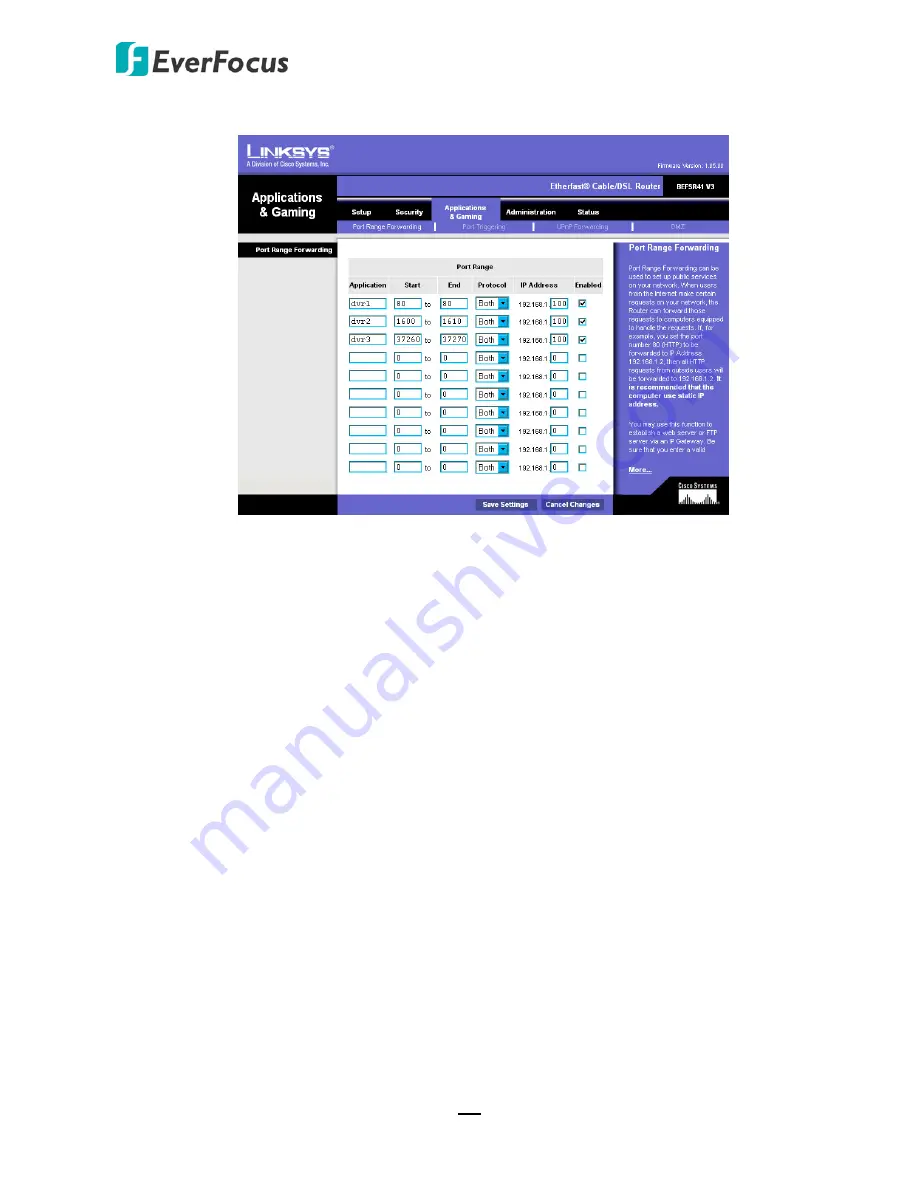
Click on the “Applications & Gaming” tab. 


Applications and Gaming allows you to set up public services on your network, such as web 
servers, ftp servers, e-mail servers, or other specialized Internet applications. (Some Internet 
applications may not require any forwarding) To forward a port, enter the information on each 
line for the criteria required. Descriptions of each criterion are described here. 


Application - 

In this field, enter the name you wish to give the application. 

Start/End - 

Enter the starting number of the range under 

Start 

and the ending number under 

End

Protocol -

 Enter the protocol used for this application, either 

TCP 

or 

UDP

, or 

Both

IP Address -

 For each application, enter the IP Address of the PC running the specific application. 

Enable -

 Click the 

Enable 

checkbox to enable port forwarding for the relevant application. 

When finished making changes, click the 

Save Settings 

button to apply your changes or 

Cancel 

Changes 

to cancel them. 


Here is an example for how the port information might look: 

HTTP 

80 to 80 


Both  192.168.1.50  Enable 


Where 192.168.1.50 is the IP address of the mobile DVR on the LAN, and the default port 80 is in 
use. 
 

Note:

 If you changed port 80 in the mobile DVR’s Network Menu, open that port instead of 80.


Summary of Contents for EMV1200 HD

Page 1: ...EMV800 HD EMV1200 HD 8 12 Channels Mobile DVR User s Manual Copyright EverFocus Electronics Corp Release Date September 2016 ...

Page 2: ...hange without notice Copyright All rights reserved No part of the contents of this manual may be reproduced or transmitted in any form or by any means without written permission of the EverFocus Electronics Corporation Windows is a registered trademark of the Microsoft Corporation Linksys is a registered trademark of the Linksys Corporation D Link is a registered trademark of the D Link Corporatio...

Page 3: ...rvicing to qualified service personnel Moisture may damage the appliance and also may cause electric shock Do not use strong or abrasive detergents when cleaning the appliance body Use a dry cloth to clean the appliance when it is dirty When the dirt is hard to remove use a mild detergent and wipe gently Do not overload outlets and extension cords as this may result in a risk of fire or electric s...

Page 4: ... servicing to qualified service personnel Power Cord Protection Power supply cords should be routed so that they are not likely to be walked on or pinched by items placed upon or against them playing particular attention to cords and plugs convenience receptacles and the point where they exit from the appliance Object and Liquid Entry Never push objects of any kind into this unit through openings ...

Page 5: ...a circuit different from that to which the receiver is connected Consult the dealer or an experienced radio TV technician for help FCC Caution Any changes or modifications not expressly approved by the party responsible for compliance could void the users authority to operate this equipment WEEE The information in this manual was current upon publication The manufacturer reserves the right to revi...

Page 6: ...12 VDC 17 2 5 Basic Connection 18 2 5 1 Power Harness Cable 19 2 5 2 Video Cable Power Out Cable 20 2 5 2 1 Camera Connection 21 2 5 2 2 Recording Resolution Table 23 2 5 3 Audio Cable 25 2 5 4 D Sub Cable 26 2 6 Monitor Connection 27 2 7 Turning On Off the Power 27 2 8 Accessing the Mobile DVR 28 2 9 Connecting the Mobile DVR to the Network 33 2 9 1 Router or LAN Connection 33 2 9 2 Direct High S...

Page 7: ... Sequence 55 4 6 Zoom 55 4 7 Archiving the Recordings or Log Data to the USB or FTP 57 4 8 Logout 60 4 8 1 Temporarily Logout 61 5 Search and Playback 63 5 1 Quick Playback 63 5 2 Playback Bar 64 5 3 Searching the Recordings for Playing Back 66 5 3 1 Time Search 66 5 3 2 Event Search 67 5 3 3 Snapshot Search 68 6 System 70 6 1 Camera 72 6 1 1 Basic Setting 72 6 1 2 Adjust Setting 74 6 1 2 1 eZ Con...

Page 8: ...1 LAN 102 6 6 2 Wireless 105 6 6 3 Mobile 107 6 6 4 Email 108 6 6 5 DDNS 109 6 6 6 FTP 115 6 6 7 Alarm Server 116 6 6 8 Remote Mobile 117 6 6 9 Network Test 118 6 6 10 Xfleet 119 6 7 Schedule Setting 120 6 7 1 Express Setup 120 6 7 2 Holidays 121 6 7 3 Schedule 122 6 8 System Setting 125 6 8 1 Date Time 125 6 8 2 Daylight Saving 127 6 8 3 User Group 128 6 8 4 User Management 130 6 8 5 I O Control ...

Page 9: ...158 7 3 3 5 G Sensor Event 160 7 3 3 6 Other 161 7 3 4 Disk 169 7 3 4 1 Disk 169 7 3 4 2 Lock Format 170 7 3 5 Display Setting 171 7 3 5 1 Monitor OSD 171 7 3 5 2 M T SEQ 172 7 3 6 Network 173 7 3 6 1 LAN 173 7 3 6 2 Wireless 176 7 3 6 3 Mobile 177 7 3 6 4 Email 178 7 3 6 5 DDNS 179 7 3 6 6 FTP 184 7 3 6 7 Alarm Server 185 7 3 6 8 Remote Mobile 186 7 3 6 9 Xfleet 186 7 3 7 Schedule 187 7 3 7 1 Exp...

Page 10: ... 7 3 11 2 Event Search 210 7 3 12 PTZ 212 8 Specifications 214 9 Troubleshooting 216 Appendix A Network Overview 217 Appendix B Linksys D Link Port Forwarding 221 Appendix C Timing of Alarm Modes 225 Appendix D Express Setup Recording Value Selection Rules 228 Appendix E IR Remote Control 230 Appendix F RTSP URL Syntax 231 Appendix G Tested Card Brands 234 Appendix H Recording Backup through EF Re...

Page 11: ...d for alarm event backup recording The User Interface has been specially designed to fit mobile small sized monitor EMV800 HD EMV1200 HD are equipped with anti shock and anti vibration housing The aviation M12 connectors are also equipped The power supply supports voltage regulator and delay on off In addition the HD mobile DVRs are SAE J1455 EN50155 E Mark CE and FCC certified You can use EverFoc...

Page 12: ...io Input 1 8 Main Monitor BNC Call Monitor Notebook PC Speaker Mouse USB Storage Device SD Card Slot 2 5 HDD x 1 HDD Key Lock WAN CMS Client PC Main Monitor RCA Function Key reserved This diagram uses EMV1200 HD as an example The EMV800 HD has 8 video inputs and 8 audio inputs The EMV800 HD EMV1200 HD have 8 12 power output sets respectively Each power out set provides 12VDC 500mA power output ...

Page 13: ...dings to the USB storage device Supports mobile applications MobileFocus Multiple network monitoring Web viewer Xfleet Server System EF Reader Windows Application Certificates CE FCC EN50155 E Mark SAE J1455 shock vibration only 3G 4G LTE function GPS function Wi Fi function Optional There are some restrictions for 1080p camera recordings Please refer to 2 5 2 1 Camera Connection for more details ...

Page 14: ...ble Audio Cable x 1 see 2 4 3 Audio Cable D Sub Cable x 1 see 2 4 4 D Sub Cable Power Out Cable x 3 EMV1200 HD x2 EMV800 HD see 2 4 2 Video Cable Power Out Cable CD x 1 Please see Note 3 Quick Installation Guide x 1 Note 1 Equipment configurations and supplied accessories vary by country Please consult your local EverFocus office or agents for more information Please also keep the shipping carton ...

Page 15: ... Function key is currently reserved 5 IR Receiver Receives data from the infrared remote control 6 System LEDs Alarm Turns on when the connected alarm I O is triggered turns off when the alarm I O stops being triggered GPS Turns on continuously when the mobile DVR is receiving GPS data System Fail Turns off when system is acting normally Turns on when these events occur System Clock Error Fan Fail...

Page 16: ...ut only works during playback Speakers with a built in amplifier and external power supply are required 10 Ethernet Port One RJ 45 port for connecting to the network 1 5 Rear Panel 1 2 3 4 5 6 7 8 9 11 12 10 EMV1200 HD 1 2 3 4 5 6 7 8 9 11 12 10 EMV800 HD No Name Description 1 Antenna 1 3G 4G Connects to the 3G or 4G Antenna for using 3G 4G LTE function 2 Antenna 2 4G Connects to the 4G Antenna fo...

Page 17: ...splaying the live view 9 Audio Input D Sub connector for connecting to the supplied Audio Cable For details please refer to 2 4 3 Audio Cable Microphones with a built in amplifier and external power supply are required 10 Video Input M12 connector for connecting to the supplied Video Cable You can then connect analog HD SD cameras to the Video Cable The MDVR doesn t support HD TVI HD CVI HD SDI ca...

Page 18: ...of the rain Where passengers can interfere with the mobile DVR Next to a heater duct The following table lists the recommended location options in the vehicle Location Convenient Operation Easy to Install Low Vibration Good Air Flow Bottom of glove box horizontal mount Yes Yes Yes Yes Bottom of passenger seat next to the driver No Yes Yes Yes Underneath bulkhead horizontal mount Yes Yes No Yes Fro...

Page 19: ...pe Bracket both of the above two mounting types are supported Please note that to meet the EN50155 standard for the mobile DVR the Z Type Bracket is required to be used If the mounting bracket you ordered is an Anti Vibration Bracket only the Support Mount is supported Please note that to meet the SAE J1455 standard for the mobile DVR the Anti Vibration Bracket is required to be used Z Type Bracke...

Page 20: ...Type Bracket 272mm 10 709 73mm 2 866 1 Attach the supplied two Z Type Brackets to the Fixing Bracket on the mobile DVR Use the supplied four Short Screws with washers to screw the Z Type Brackets to the Fixing Bracket Z Type Bracket Fixing Bracket 2 Screw the mobile DVR to the surface using the supplied four Long Screws with washers ...

Page 21: ...6 3mm 5 4 63 4mm 2 5 178mm 7 50mm 1 969 229 6mm 9 207 4mm 8 2 235 7mm 9 3 218mm 8 6 192mm 7 6 Ø5 5mm Ø0 2 The Anti Vibration Bracket is already installed on the mobile DVR Users need to prepare four screws to screw the mobile DVR onto a surface The screw diameter on the Anti Vibration Bracket is Ø5 5mm Ø0 2 ...

Page 22: ...the mobile DVR before removing the hard disk Also ensure to remove the hard disk only after the power was completely shut off This would protect and extend the operating life of the hard disk 1 Make sure the mobile DVR is powered off and unlock the HDD Tray using the supplied key Locked Unlocked 2 To install the HDD press the Release Latch to the right and the Locking Arm will pop up Release Latch...

Page 23: ...k inside the HDD Tray insert a HDD in the HDD Tray and then screw the HDD to the tray with the supplied 8 screws 5 Insert the HDD Tray into the drive bay and close the Locking Arm until you hear a click 6 Lock the HDD Tray before you power on the mobile DVR Locked Unlocked ...

Page 24: ...le DVR unscrew the SD card protection plate 2 Lift up the SD card protection plate and then insert a SD card 3 Screw back the SD card protection plate The SD card installation is now complete The Mobile DVR will automatically detect when a new SD card has been inserted and the below SD card format message will pop up Click Yes to format the SD card The formatting process will take about 30 60 seco...

Page 25: ...hen card space is full The mobile DVR will automatically pop up a SD Card Disk Full message for notification Users will have to replace a new SD card or backup the SD card recordings and then erase format the recordings to resume the alarm event backup recording function To enable the Record Overwrite function please go to the OSD menu System Record Playback Record To remove the SD card please go ...

Page 26: ...are the video input audio input power output numbers 2 4 1 Connecting to a Truck with 24 VDC Glove box inside or underneath Driver s seat between the seat and the back panel or underneath the Passenger seat 24V Red IGN Yellow Relay 24V EMV1200 HD Rear Panel GND Black Vehicle Battery 24V Power Harness Cable Fuse 15A L o c k ACC On P o w e r ACC Note 1 If the car is without an ignition key please co...

Page 27: ...CC EMV1200 HD Rear Panel Note 1 If the car is without an ignition key please connect the IGN yellow wire directly or via a switch to the vehicle battery 2 It is suggested to use a relay in the installation Otherwise the mobile DVR will always draw the power from the vehicle battery Trunk Passenger seat underneath Glove box inside or underneath Driver seat between the seat and side panel ...

Page 28: ...ts please refer to 2 5 Monitor Connection 4 To listen to audio of video source connect a speaker to the Audio out RCA socket Note that the speaker with a built in amplifier and external power is required 5 To manage the mobile DVR over network use a standard RJ 45 cable to connect the mobile DVR to the network Note The mobile DVRs feature Wi Fi 3G 4G function You can optionally connect Wi Fi 3G 4G...

Page 29: ...ollowing figure uses EMV1200 HD as an example IGN Yellow DC Power In Red GND Black 9 VDC 36 VDC Pins on Power Cable Power Input EMV1200 HD Rear Panel Power Harness Cable Pin Assignment No Color Description No Color Description 1 Red DC Power Input 5 Black GND 2 Red DC Power Input 6 Black GND 3 Red DC Power Input 7 Yellow IGN 4 Black GND ...

Page 30: ...n ports on the mobile DVR If the Video Cable connects to 5 8 CH Video In port the cable labeled as VIN 1 will be channel 5 and so forth The following figure uses EMV1200 HD as an example EMV1200 HD Rear Panel Video Input Ports Camera 5 8 Video Cable Camera 1 4 Video Cable Camera 9 12 Video Cable Power Out Cable 1 12 You can also use the supplied Power Out Cable to power on the connected cameras On...

Page 31: ... 720p D1 cameras the mobile DVR will display and record 12 EMV1200 HD 8 EMV800 HD channels of 720p D1 live streams and recordings 4 All video inputs are compatible with all resolution types of cameras such as 1080p 720p and D1 cameras HD TVI HD CVI HD SDI cameras are not supported However the same types of cameras should be connected to the same pair of video inputs Otherwise only the camera live ...

Page 32: ...erent types of cameras to the same pair of video inputs it will only display the camera live view with the higher resolution As to the channel of lower resolution camera there will be no live view and a status icon will be displayed Example A If you connect a 1080p camera to CH1 and either a 720p or D1 camera to CH2 only 1080p stream will be displayed and CH2 will have no live view but a status ic...

Page 33: ...are connected to the channels Let s take a look at the EMV1200 HD Maximum Recording Resolution Table Case 1 illustrates that when 6 1080p cameras are connected to Ch1 3 5 7 9 11 and the rest channels are connected with no camera the mobile DVR is able to record 6 1080p camera recordings Case 2 illustrates that when 5 1080p cameras are connected to Ch1 3 5 7 9 and the last pair of video input is co...

Page 34: ...80 720p 1280x720 D1 704x480 1080pH 960x1080 3 Main Stream frame rate 1080p 1080pH 15FPS 720p D1 30FPS 4 Sub Stream frame rate 352x240 30FPS 176x120 30FPS 5 1080pH only activates when 2 1080p cameras are connected to the same pair of video inputs 6 N A indicates that no camera is connected to the channel EMV800 HD Maximum Recording Resolution Table Ch Case 1 Case 2 Case 3 Case 4 Case 5 Case 6 Case ...

Page 35: ...or connecting 8 microphones using the supplied Audio Cable The Audio Cable is labeled with AIN 1 AIN 8 Microphones with a built in amplifier and external power supply are required The following figure uses EMV1200 HD as an example EMV1200 HD Rear Panel Audio Input Audio Input 1 8 Audio Cable ...

Page 36: ... 8 white wires RS 232 Tx Rx 2 yellow wires RS 232 Tx Rx 3 green wires Alarm Out 1 gray wires Alarm Out 2 purple wires RS 485 blue wires GND black wires 26 Pins on D Sub Cable Pin Pin Assignment Pin Pin Assignment Pin Pin Assignment 1 Alarm Output N O 1 10 Alarm Input Alarm in 1 18 GND 2 COM 1 11 Alarm in 2 19 RS 232 Tx 2 3 N C 1 12 Alarm in 3 20 RS 232 Rx 2 4 N O 2 13 Alarm in 4 21 GND 5 COM 2 14 ...

Page 37: ...Cable RCA Cable Main Monitor Main Monitor Front Panel Rear Panel 2 7 Turning On Off the Power Before powering on the mobile DVR please make sure the internal HDD have been installed properly Once you have completed the basic cable connections you are ready to turn on the mobile DVR Simply plug in the power source The POWER LED will light up if power is normal Once the system has finished loading y...

Page 38: ... aspx Please connect the DVR on the same LAN of your computer 1 Save IP Utility Setup exe in your computer Double click the exe file and follow the on screen instructions to install the IP Utility 2 Click the Finish button the IP Utility will be automatically launched to search the IP devices connected on the same LAN 3 To optionally configure the Machine Name IP Address IP Type or Port Number usi...

Page 39: ...log in several DVRs at once c Right click the column to configure the setting Click Apply Changes button to apply and save the settings Note Most networks uses DHCP to assign IP address if you are unsure of your network settings please consult your network administrators for configuration details 4 To access the Live View window double click the IP address of the desired device the login window po...

Page 40: ...and password to log in again By default the user ID is admin and the password is 11111111 Note for the first time login The Download ePlayer Instruction page will only be prompted for the first time login in order to update the system to the latest plugin version When the Plug in blocked appears on the browser select Always allow plug ins on xxx click Done and then reload the webpage 6 Now you wil...

Page 41: ...e remote Web interface please see below If the Error window appears please be sure to close ALL the Web browser windows first and then click Retry When the Completing the ePlayer Setup Wizard window shows up click Finish Then you can open a new browser again to access the DVR s remote Web interface ...

Page 42: ...t Explorer right click the browser and then click Run as administrator You may need to turn User Account Control off if you still can t see the Remote Live View On the computer click Start Control Panel System and Security Action Center click Change User Account Control Settings the User Account Control Settings window appears Adjust the slide bar to Never Notify and then click OK Restart your com...

Page 43: ...rface please refer to 7 Remote Access to the Mobile DVR To set up port forwarding please consult the manual of the router or refer to Appendix B Linksys D Link Port Forwarding High speed modem Internet Straight through LAN patch cable Router Cat 5 Straight Through Cable Left Pinout of a straight through cable Connection Procedure The First step is to purchase or make a straight through cable We re...

Page 44: ...Windows Vista look for the information that says IP v4 Take the values for Subnet Mask and Default Gateway and input them into the mobile DVR these values should be exactly the same in both devices However you should change the last number of the IP address For example if the IP address of the computer is 192 168 2 101 the mobile DVR s IP address should be 192 168 002 050 To access the mobile DVR ...

Page 45: ...ing a Linksys or D Link router see Appendix A for basic support on setting up ports For any other router you will need to contact the manufacturer for support To access the mobile DVR from a computer simply open Internet Explorer and in the address bar type http the IP address given by your internet service provider Note If you changed to a different port other than 80 you will need to include thi...

Page 46: ...e Please remember you can not use a cross over network cable for this application Once you have a straight through cable plug one end into the LAN port on the back of the recorder and the other into the high speed modem Log into the EverFocus mobile DVR menu and go to the Network Setting Menu Input the Static IP address the Subnet Mask and the Gateway that you obtained from the internet service pr...

Page 47: ... have never made a cross over cable Please remember you can not use a straight through network cable for this application Once you have a cross over cable plug one end into the LAN port on the back of the mobile DVR and the other into the network card on the back of the computer Log into the EverFocus mobile DVR menu and go to the Network Setting Menu You must use the Static IP option for this typ...

Page 48: ...EMV800 HD EMV1200 HD Mobile DVR 38 Go to Start Double click on Control Panel Click Network and Sharing Center Click Local Area Connection ...

Page 49: ...EMV800 HD EMV1200 HD Mobile DVR 39 Click Properties Click on Internet Protocol Version 4 TCP IPv4 and then click Properties ...

Page 50: ...an IP address of 192 168 1 2 a Subnet Mask of 255 255 255 0 and a Default Gateway of 192 168 1 1 and then click OK Restart both of the computer and the mobile DVR To access the mobile DVR from the computer simply open Internet Explorer and in the address bar type http 192 168 1 3 ...

Page 51: ...l Enable Audio Out To select a channel on the Live View window single click on the desired channel screen The selected screen will be highlighted by a red frame To toggle full screen of a channel double click on a desired channel To switch the Audio Output channel single click on the desired channel screen the highlighted channel will be automatically applied with the Audio Output function an audi...

Page 52: ...ield Input Options You may found the following fields in the Configuration menu Follow the instructions below to configure the settings Text Box Click on the box and an on screen keyboard will appear On Screen Keyboard Click on a button to input that character The buttons on the right and bottom have the following functions Caps Switch to capital letters Delete the letter backwards Confirm the sel...

Page 53: ...own arrow to see all selections then directly click on an option to select it Check Box Click on the box to enable it checked or disable it unchecked Button Click the button to execute the function Bar Slide the bar to the left or right for adjusting the set point ...

Page 54: ...rs 2 Select the user name from the User name drop down list and input the password The default user name and password are User Name admin Password 11111111 Note For details on setting up multiple user accounts please refer to 6 8 4 User Management To input the password click the Password field to bring up the on screen keyboard Click on each button to input the desired characters When finished cli...

Page 55: ... Mode box 3 Click Login to log in the mobile DVR Note This verification code is effective within 24 hours only so please set up a new password in the System Setting page refer to 6 8 4 User Management 3 2 3 Camera Selection You can control each camera individually by selecting that camera To select a camera follow the instructions below Click a camera on the screen and the selected camera will be ...

Page 56: ...a Camera Status 3 Click the Set button of the analog camera 4 Check the box to enable the Record Audio option and select an audio input device You can select multiple cameras to one single audio input device Note that the mobile DVR only provide one channel audio output You can switch the Audio Output function to either one from the cameras To switch the Audio Output function to the desired camera...

Page 57: ...ding videos For details please refer to 5 Search and Playback 2 PTZ Click to display the PTZ Control Panel for controlling the connected PTZ cameras For details please refer to 4 1 PTZ 3 Layout Click to display the Layout Bar as shown below Select a layout type for the live view display on the Main Monitor For details please refer to 4 2 Layout Switching Chapter 4 ...

Page 58: ...or To switch to the Main Monitor click the button Note that the Call Monitor can only be used to display camera views The functions including the layout channel switching icon display sequencing mode of the Call Monitor can only be configured on the Main Monitor 8 Zoom Click to enter the Zoom mode You can zoom in the camera view up to x4 and navigate the camera view For details please refer to 4 6...

Page 59: ... the camera a Move the PTZ camera to the desired position b Click the Preset button c Set up a preset number for the current position by clicking the number buttons The number will be displayed in the number box d Click the Set button to save the settings 6 To jump to a Preset Position a Click the Preset button b Click the desired Preset number c Click the Go button 7 Shortcut for Preset 1 9 a Cli...

Page 60: ...er c Click the Delete button Click C to clear the entered number in the Number Box Click at the top right corner to hide the PTZ Control Panel see 4 1 1 Express Control of PTZ To display the PTZ Control Panel right click on the screen Click Exit PTZ to close the PTZ Control Panel and exit the PTZ mode Note Before start using the Auto Pan Pattern and Tour functions you have to configure the related...

Page 61: ...rection focus and zoom by clicking directly on the screen Direction Controls When your mouse cursor turns into a direction icon click on the screen will force the camera to turn in that direction Focus Controls When your mouse cursor turns into click on the screen will focus closer the image When your mouse cursor turns into click on the screen will focus farther the image Zoom Controls When your ...

Page 62: ...enu 2 Click the Layout icon 3 Click on the desired layout 4 3 Channel Switching You can switch the selected camera to a specific channel Follow the steps below 1 On the live view screen select a camera the selected camera will be highlighted with a red frame 2 Right click to display the OSD Root Menu 3 Click the Change Channel icon the Channel Bar appears 4 Select a channel the selected camera wil...

Page 63: ...f each camera stream to inform the correct camera type to be connected Not 1080p Camera Not 720p Camera 3 The following icons will be displayed at the top left side of each camera stream to show each camera s status Recording Playback Fast forward Fast backward Back pause Alarm Motion Video loss Uninstall Audio On Audio In 4 The following icons will be displayed at the bottom of the monitor to sho...

Page 64: ... bottom of the monitor to show the CAN bus status To enable CAN bus status please consult EverFocus for more details ts everfocus com tw Turn Left Turn Right Reverse Brake 3G Network 4G Network WiFi Network GPS No Signal of Wireless Network Wireless Network Off Low Beams High Beams ...

Page 65: ...h a dwell time of 3 seconds each repeated Please refer to 6 5 2 M T SEQ for detailed information 4 6 Zoom You can zoom in the camera view up to 4X and navigate the camera view using the mouse To enter the Zoom mode 1 Select a camera and then click the Zoom button on the OSD Root Menu to zoom in the camera view to 2X The ZOOM 2X stamp will be displayed on the top screen 2 Navigate the camera view t...

Page 66: ...MV800 HD EMV1200 HD Mobile DVR 56 3 Right click the screen the Zoom Bar appears in the middle of the screen 4 Click to zoom in the camera view up to 4X 5 Click the Logout button to log out the Zoom mode ...

Page 67: ...f selected cameras from main stream or sub stream Player Check the box to include the EFPlayer program in the copy You can use the EFPlayer on a computer to play back the recordings Please see the instruction the next page Start Date Time Click to bring up the on screen keyboard clock to select the start date time End Date Time Click to bring up the on screen keyboard clock to select the end date ...

Page 68: ...rt time date current playback time recording end time date 2 Load Click to select a recording file and open it 3 Save as AVI Click to archive the recording file of 1 channel and save as AVI format 4 Time Search Click to search a recording from a selected time 5 Channel Switch Click to switch channel bar between CH1 16 and CH17 32 6 Time Bar Move the time bar to a desired time to play back the reco...

Page 69: ...rag to increase or lower the volume 11 Scale Out In Click to adjust time scale 12 Screen Division Click to display the channels to fit the screen Click to select a desired screen division display mode 1 4 9 16 screen division display modes If the channels are more than the screen divisions you can select the same screen division display mode to change the channels on the screen 13 Speed Shows the ...

Page 70: ...the Logout Confirmation window Click Yes when you are ready to logout of the system You will need to login again before accessing the OSD Root Menu If you do not need the Login Logout step before entering the Root Menu please uncheck the Login box in the User Management setting page For more details please refer to 6 8 4 User Management ...

Page 71: ... in conjunction with the Covert Camera function Once you click the Exit icon the camera streams will be hidden on the Live View Sequence Mode However the mobile DVR will still record the videos and the recordings can be played back To enable the Temporarily Logout function follow the steps below 1 Ensure the Login box is Unchecked OSD Root Menu System System Setting User Management ...

Page 72: ...oot Menu System Camera Basic 3 Click the Exit icon on the OSD Root Menu the Logout menu appears 4 Click the Yes button and the selected camera streams will be hidden on the Live View Sequence Mode 5 To disable the Temporarily Logout function simply right click the screen to bring up the OSD Root Menu and then you can start controlling the mobile DVR ...

Page 73: ...ck Playback box in the Record setting page OSD Root Menu System Record Playback Playback to enable the configured time in the field below 2 Enter the desired time for playing back the recording Take 60 seconds for example if the current system clock time is 17 35 00 the start time for the playback recording will start from 17 34 00 60 seconds ago from 17 35 00 3 On the Live View Window select a de...

Page 74: ...Bar Green Normal Orange Motion Blue Video Loss Red Alarm Event 3 Playback Speed Indicates the current Playback Speed 4 Express Copy Click to bring up the Copy menu for archiving the recordings log data to the USB storage device or DVD burner For details please refer to 4 7 Archiving the Recordings or Log Data to the USB or FTP 5 Close Click to hide the Playback Bar To bring up the Playback Bar aga...

Page 75: ...is 2 weeks L3 Entire Time Bar scale is 1 week L4 Entire Time Bar scale is 1 day L5 Entire Time Bar scale is 1 hour L6 entire Time Bar scale is 30 minutes 13 Time Bar Scale Use the and buttons to adjust the time scale range for the bar The scale range includes 6 options levels When changing the level the Start Time and End Time will change 14 15 Start Time Indicates the playback start time 16 Curre...

Page 76: ...arch menu select Time Search Event Search or Snapshot Search to enter to the setup menu To bring up the Search menu Right click to bring up the OSD Root Menu and then click the Search button 5 3 1 Time Search Start Date Click to bring up the on screen keyboard to select the date Start Time Click to bring up the on screen clock to select the time Play Click to start playing back ...

Page 77: ...o start searching The search results will be listed in the Event List menu as shown below Copy to Select a destination USB or FTP for the recordings to be copied to Player Check the box to include the EFPlayer program in the copy You can use the EFPlayer on a computer to play back the recordings To use the program please refer to 4 7 Archiving the Recordings or Log Data to the USB or FTP Copy Clic...

Page 78: ... on screen clock to select time Search Direction Click to search forward backward based on the setup time above Search Camera Select a desired camera to be searched Result Interval Click to set up the interval for the snapshots of the video frame For example if you select 5 minutes the video frame will be snapshotted with 5 minute interval see image below Search Click to start searching The search...

Page 79: ...e interval 2 Right click on the screen the Resume Playback Bar appears in the middle of the screen Previous Play Close Next 3 Click the Previous or Next buttons to display the previous next snapshots 4 Select a snapshot by clicking on the snapshot the selected snapshot will be highlighted with a white frame 5 Click the Play button to resume the video 6 Click the Close button to close the Resume Pl...

Page 80: ...upplied IR Remote Control The following operations are examples of using a Mouse This chapter describes the functions and options of the System Setting in the on screen display OSD menus Right click the mouse the OSD Root Menu appears Click the System button the following Configuration Menu displayed with 9 setup options appears Chapter 6 ...

Page 81: ...Other 6 4 Hard Disk 6 4 1 Disk 6 4 2 SD Card 6 4 3 Lock Format 6 5 Display Setting 6 5 1 Monitor OSD 6 5 2 M T SEQ 6 6 Network 6 6 1 LAN 6 6 2 Wireless 6 6 3 Mobile 6 6 4 Email 6 6 5 DDNS 6 6 6 FTP 6 6 7 Alarm Server 6 6 8 Network Test 6 6 9 Remote Mobile 6 6 10 Xfleet 6 7 Schedule 6 7 1 Express Setup 6 7 2 Holidays 6 7 3 Schedule 6 8 System Setting 6 8 1 Date Time 6 8 2 Daylight Saving Time 6 8 3...

Page 82: ...le the selected camera If this box is unchecked the mobile DVR will not get the camera streaming Covert Check the box to hide the camera stream in Live View and Sequence modes However the MDVR will still record the videos and the recordings can be played back by users who have the privilege to playback For details on enabling the Covert function please refer to 4 8 1 Temporarily Logout Record Mode...

Page 83: ...andard High and Superior The higher the quality the more the HDD space is used Normal Speed Select a frame rate per second FPS for continuous recording The speed is limited by the maximum total recording capacity of the MDVR as allocated across all the installed cameras with upper limit of 30 FPS NTSC 25 FPS PAL per individual camera respectively real time recording Event Speed Select a frame rate...

Page 84: ... to adjust the following settings Brightness Move the bar to adjust the brightness Contrast Move the bar to adjust the contrast Color Move the bar to adjust the color Advanced Click to enter the camera s OSD menu for controlling and adjusting the camera s setting Please see the figure and instructions on the next page Save Click to save the settings ...

Page 85: ...ply on the monitor at the DVR end as illustrated in Diagram B Traditional Way to Control Camera OSD Control Camera OSD at Camera End A Camera End DVR End Use eZ Controller to Control Camera OSD B Camera OSD Control Directly at DVR End DVR End Camera End 1 On the Adjust setting page Select the camera you want to adjust 2 Click the Advanced button and the camera live view with its OSD menu will disp...

Page 86: ...e will automatically pop up Schedule Record Check the box to record by the schedule to the hard disk Please see 6 7 Schedule Setting for more details Time Stamp Select Top Bottom to overlay time information on the top bottom of the recording streams Select Off to disable the function Record Status Relay Output Select a number to monitor the recording status of the selected alarm relay The recordin...

Page 87: ...please refer to 5 1 Quick Playback Quick Playback Check the box to enable the Quick Playback function as described below Playback From X Seconds ago When the mobile DVR is put into playback mode it will begin playing from the selected time Choose from 60 to 3600 seconds prior to the present time Save Click to save the settings ...

Page 88: ...at the pre alarm recording rate will follow the Normal Speed configured in the earlier section see 6 1 1 Basic Setting Buzzer Check the box to enable the buzzer when an alarm event is triggered Email Notify Check the box to send email notification with a snapshot file when an alarm event is detected Email operation requires valid email entered in the Email setup menu see 6 6 4 Email Network Alarm ...

Page 89: ...output will last for the setup duration time 10 150 seconds Permanent Alarm will remain active until the user presses the Enter key on the IR Remote Control or resets the alarm remotely Transparent Alarm output remains as long as the alarm input is active Trans Timeout Alarm output continues until event ends then continues for the setup duration time 10 150 seconds Timeout Duration This function o...

Page 90: ...cted Email operation requires valid email entered in the Email setup menu see 6 6 4 Email Network Alarm Check the box to send out a network alarm to a client PC when video loss event occurs This feature works with EverFocus CMS software You will need to configure the Alarm Server for the mobile DVR to send network alarms to the client PC see 6 6 7 Alarm Server Alarm Output Select an alarm output n...

Page 91: ...output continues until event ends then continues for the setup duration time 10 150 seconds Timeout Duration This function only appears when you select Timeout or Trans Timeout options in the Output Type drop down list Select a duration time for the motion event The alarm output will last for the setup duration time between 10 and 150 seconds Apply To Click the button to apply the same settings to...

Page 92: ...ee 6 1 1 Basic Setting Buzzer Check the box to enable the buzzer when a motion event is triggered Email Notify Check the box to send email notification when a motion event is detected Email operation requires valid email entered in the Email setup menu see 6 6 4 Email Network Alarm Check the box to send out a network alarm to a client PC when motion occurs This feature works with EverFocus CMS sof...

Page 93: ...ontrol or resets the alarm remotely Transparent Alarm output remains as long as the alarm input is active Trans Timeout Alarm output continues until event ends then continues for the setup duration time 10 150 seconds Timeout Duration This function only appears when you select Timeout or Trans Timeout options in the Output Type drop down list Select a duration time for the motion event The alarm o...

Page 94: ...otion area drag a rectangle with your mouse from bottom to top lower right to upper left 5 Follow Step 3 to set up multiple motion areas if necessary 6 Sets up the Sensitivity and Min Area for the motion grids Sensitivity Sets up the motion sensitivity for the grids The larger the number the higher the sensitivity Min Area This function is designed to prevent false detections caused by small objec...

Page 95: ... see 6 6 4 Email Network Alarm Check box to send out a network alarm to the client PC This feature works with EverFocus CMS software You will need to configure the Alarm Server for mobile DVR to send network alarms to the client PC see 6 6 7 Alarm Server Alarm Output This will transmit a signal through the alarm output relay It can be set to either NONE not active 1 active or 2 active Output Type ...

Page 96: ...t and then set the latitude Radius Select radius value from kilometer Km or mile Mi If you select Rectangle in the GPS Border Type field the following settings will appear Upper Left Latitude Select S South or N North and then set the latitude Upper Left Longitude Select E East or W West and then set the latitude Lower Right Latitude Select S South or N North and then set the latitude Lower Right ...

Page 97: ...software You will need to configure the Alarm Server for mobile DVR to send network alarms to the client PC see 6 6 7 Alarm Server XY Axial Trigger Value Set XY Axial trigger value alarm will be triggered when acceleration reaches this value in horizontal direction with respect to the horizon The available setup value is between 0 127 1000mg 1 Gravity Z Axial Trigger Value Set Z Axial trigger valu...

Page 98: ...resses the Enter key or resets the alarm remotely Transparent Alarm output remains active until event ends Trans Timeout Alarm output continues until event ends then continues for the set time duration Timeout Duration The amount of time the buzzer sounds when GPS is lost Duration selectable from 1 to 150 seconds Save Click to save the settings ...

Page 99: ...ent is detected Email operation requires valid email entered in the Email setup menu see 6 6 4 Email Network Alarm Check the box to send out a network alarm to a client PC when an alarm event occurs This feature works with EverFocus CMS software You will need to configure the Alarm Server for the mobile DVR to send network alarms to the client PC see 6 6 7 Alarm Server Alarm Output Select an alarm...

Page 100: ...is feature works with EverFocus CMS software You will need to configure the Alarm Server for the mobile DVR to send network alarms to the client PC see 6 6 7 Alarm Server Stop Recording Check box to stop recording when System HD s temperature is over the Temp Warning Limit Temp Warning Limit Sets the trigger temperature for System HD Temperature event actions Choose between 45 C 113 F and 70 C 158...

Page 101: ...ck the box to send out a network alarm to a client PC when HD fails This feature works with EverFocus CMS software You will need to configure the Alarm Server for the mobile DVR to send network alarms to the client PC see 6 6 7 Alarm Server Alarm Output Select an alarm output number When an alarm is triggered the signal will be transmitted through the selected alarm output relay Output Type Output...

Page 102: ...gnal will be transmitted through the selected alarm output relay Output Type Select an output type when HD is full Timeout Select this option and then set up the Timeout Duration in the field below the alarm output will last for the setup duration time 10 150 seconds Permanent Alarm will remain active until the user presses the Enter key on the IR Remote Control or resets the alarm remotely Transp...

Page 103: ...ed through the selected alarm output relay Output Type Select an output type when HD is off Timeout Select this option and then set up the Timeout Duration in the field below the alarm output will last for the setup duration time 10 150 seconds Permanent Alarm will remain active until the user presses the Enter key on the IR Remote Control or resets the alarm remotely Transparent Alarm output rema...

Page 104: ...Email Network Alarm Check the box to send out a network alarm to a client PC when power has been restored This feature works with EverFocus CMS software You will need to configure the Alarm Server for the mobile DVR to send network alarms to the client PC see 6 6 7 Alarm Server Save Click to save the settings Note As alarms and emails cannot be transmitted without power the log entry is made when ...

Page 105: ...tive until the user presses the Enter key on the IR Remote Control or resets the alarm remotely Transparent Alarm output remains as long as the alarm input is active Trans Timeout Alarm output continues until event ends then continues for the setup duration time 10 150 seconds Timeout Duration This function only appears when you select Timeout or Trans Timeout options in the Output Type drop down ...

Page 106: ... signal will be transmitted through the selected alarm output relay Output Type Select an output type when the network is lost Timeout Select this option and then set up the Timeout Duration in the field below the alarm output will last for the setup duration time 10 150 seconds Permanent Alarm will remain active until the user presses the Enter key on the IR Remote Control or resets the alarm rem...

Page 107: ...e Start Shows the earliest recording time of the mobile DVR Record Time End Shows the latest or most current time on the mobile DVR Disk Select a disk number Health Status Displays the current status of the selected disk Disk Temperature Displays the current temperature of the selected disk Disk Size Total Shows the total space of the selected disk Disk Size Usage Shows the used space of the selec...

Page 108: ...R please click the Unmount SD button first for data safety purpose Format SD Click the button to format the SD card After formatting the SD card all the recordings will be erased and 5 of the card space will be reserved for system use If you want to back up the recordings you can use EverFocus EF Reader to remotely locally back up the recordings from the SD card see Appendix H Recording Backup thr...

Page 109: ... amount of locked event recordings has reached the maximum lock percentage the mobile DVR will be unable to lock new event recordings Unlock All Click this button to unlock the locked part of hard disk Delete All Click this button to delete all the unlocked data in the hard disk WARNING This will effectively ERASE the hard disk s contents except for the locked portion Format Disk Click this button...

Page 110: ...onitor Call Monitor Title Check the box to display camera titles Date Time Check the box to display current date time Event Status Check the box to display event status HDD Status Check the box to display hard drive status Playback Date Time Check the box to display playback date time only for main monitor Playback Status Check the box to display playback status only for main monitor GPS Status Ch...

Page 111: ... Call monitor The Sequence will repeat continuously from step 1 to step 20 until interrupted Monitor Drop Down Select Main Monitor or Call Monitor Step The sequencing order Camera Select a camera for the specific step Dwell sec Sets up the dwell time between 0 and 60 seconds for each step Save Click to save the settings ...

Page 112: ... 1 LAN According to your network environment select Static IP DHCP or PPPoE to configure an IP address to the mobile DVR LAN Port Select LAN1 or LAN2 from the drop down list It s recommended to use LAN 1 for connecting to the MDVR via a hub or switch and use LAN 2 for WAN connection Network Type Three options are selectable Static IP DHCP and PPPoE Static IP User can set a fixed IP for network con...

Page 113: ...tion Save Click to save the settings Additional information 1 Set up the mobile DVR Network Menu according to the instructions detailed in the Networking chapter of this mobile DVR s manual a If using DHCP all settings will be detected automatically While DHCP is a useful tool for determining the network settings if you set up your mobile DVR in this manner its IP address may change at different t...

Page 114: ...Web browsing Because of this in order to prevent the average user from hosting a Web server most ISPs BLOCK traffic using port 80 from reaching the average site If you only plan to view your mobile DVR on a LAN you can use port 80 and don t have to concern yourself with DDNS or routers However if you desire remote access to your mobile DVR perhaps using DDNS optional you MUST select functional por...

Page 115: ...k If DHCP is selected this value will be assigned automatically Gateway Displays the gateway on your network for the mobile DVR to use when communicating with any devices not on the local network If DHCP is selected this value will be assigned automatically DNS Server 1 Displays the primary DNS server for your network If DHCP is selected and an internet connection is available this value should be...

Page 116: ...ile DVR It s recommended to select Auto when there is more than one mobile DVR set up in the same wireless network environment Security Mode Select a wireless encryption protocol WEP WPA and WPA2 WPA Algorithms Select a WPA algorithm from the drop down list Save Click to save the settings ...

Page 117: ... Select On from the GPRS Service drop down list and select an authentication CHAP or PAP 3 Insert the APN Dial Number User Name and Password provided by the network service provider and then click the Connect button The connection status will be displayed in the Status field below If it s connected successfully the status will display Success And the Date Rate information will be displayed in the ...

Page 118: ...uthentication Password Input the password if the SMTP server requires authentication Confirm Input the password again to confirm the password Sender Email Input the e mail address of the sender the mobile DVR Sender s e mail address has to match the user name and password above Receiver Email 1 Input the first e mail address that event messages are sent to Receiver Email 2 Input the second e mail ...

Page 119: ... trouble of checking if the IP address assigned by DHCP Server has changed Once the IP is changed the mobile DVR will automatically update the information to the DDNS to ensure it is always available for remote access Before enabling the following DDNS function user should have applied for a host name from the DDS service provider s website We support two DDNS server providers www everfocusddns co...

Page 120: ...the text field size on the OSD you can move your cursor onto the text field to display the entire name on the OSD Note that the name of the mobile DVR cannot include a space underline or any special characters particularly _ Save Click to save the settings Note 1 It is not necessary to append the HTTP port number to the DDNS name The EverFocus DDNS server not only keeps track of your mobile DVR s ...

Page 121: ... 111 To set up DDNS function 1 In order to allow remote access to the MDVR from outside of the local network enable either the Port Forwarding or DMZ function of your router Please refer to the manual of your router for more details ...

Page 122: ...vice provider for the information of subnet mask default gateway and the DNS Server 1 If DHCP is selected The IP address subnet mask default gateway and the DNS Server 1 will be assigned automatically by DHCP server If PPPoE is selected Enter the User Name e g xxxx hinet net and Password provided by your ISP service provider 3 On the DDNS setting page register a free host name from EverFocus DDNS ...

Page 123: ...ost name should not include a space underline or any special characters particularly _ c Click Save 4 The DDNS setup is now complete Open a browser and enter the domain name http host name everfocusddns com in the address field The Web interface of the MDVR should be displayed For example if you ve obtained the host name HQtest from EverFocus DDNS server enter http HQtest everfocusddns com in the ...

Page 124: ... dyndns org from the DDNS Service drop down list 4 Enter the host name in the Host Name field Note that the name of the mobile DVR cannot include a space underline or any special characters particularly _ _ 5 Enter the User Name Password of the dyndns account 6 The setting is complete And you should now be able to remotely connect the mobile DVR by typing the name you created into the address bar ...

Page 125: ...s or snapshots please see 6 2 1 Alarm and 6 3 3 Motion FTP Server Enter the IP address or the host name of the FTP server Port Enter the port number for the FTP server Default is 21 User Name Set FTP User s name Password Set FTP password Confirm Input the FTP password again to confirm File Name Enter the file name Save Click to save the settings Note If you want to upload recordings to the FTP ple...

Page 126: ...The network alarm can be transmitted to up to 3 addresses Protocol Select the protocol type for alarm transmission Note the protocol selected here should match the protocol set up for the CMS alarm server UDP User Datagram Protocol TCP Transmission Control Protocol Port Select the transmission port for network alarm messages The port setup here should match the port set up for the CMS alarm server...

Page 127: ...u also want to use the FTP function for uploading the recordings MP4 video format please select the H 264 codec H 264 The H 264 codec is compatible with iOS and Android MobileFocus applications and IE Web browser viewing on iPhone iPod touch iPad Android and BlackBerry MJPEG The MJPEG codec is compatible with iOS and Android MobileFocus applications and IE Web browser viewing on iPhone iPod touch ...

Page 128: ...connectivity problems by obtaining responses from nodes progressively farther along the network DNS functionality can also be confirmed by entering a valid DNS name instead of an IP address To verify basic network connectivity between the mobile DVR and other LAN or WAN nodes click the Ping button ...

Page 129: ...f fleet vehicles on a Web browser anywhere and anytime With Xfleet not only can you reduce overall costs by effectively utilizing resources such as vehicles fuel and manpower but you can improve the management efficiency and business performance by keeping and analyzing the historical records graphical reports of the vehicle data as needed OK To successfully establish the connection between the MD...

Page 130: ...e begins Daytime End Select a weekday end time Nighttime schedule ends when Daytime ends Record Type Select a recording type for each time period Disable No recording during the scheduled time period Normal Event Continuous and Event recordings Event Only Event recordings only Normal FPS Set up the fps for continuous recording Event FPS Set up the fps for event recording Action Check the box to en...

Page 131: ...e Disabled Select to disable the Holiday Others recording schedule One time Select this option and then set up the specific date and year in the Details field The mobile DVR will start recording on this specific date Month date Select this option and then set up the specific date in the Details field The mobile DVR will start recording on this date yearly Month Weekday Select this option and then ...

Page 132: ...e block for Holiday Hol Other Oth Sunday Sun Monday Mon Tuesday Tue Wednesday Wed Thursday Thu Friday Fri or Saturday Sat Time 0 23 The numbers represent the 24 hours of a day Time Bar The time bar uses three different colors to distinguish each recording mode Gray No Rec No recording during this time block Pink E Only events are recorded during this time block Blue green N E Default Normal and ev...

Page 133: ...mezone button to edit the recording parameters for a time zone Editing Timezone From Displays time zone start time To Displays time zone end time Record Displays Record mode Resolution Recording resolution is displayed Normal Frame rate in FPS for continuous recording It is important to keep track of the normal recording resources being allocated at each hours of the day Increasing the Normal reco...

Page 134: ...eck this box to enable notifications enabled elsewhere Buzzer Alarm out E mail and Network Alarm when an event occurs Apply to Days This button can be used to copy schedules to other days Select which days you wish to copy to Select All selects all days Clear All deselects all days Click OK to copy the settings or Cancel to exit without copying Apply to Cameras This button can be used to copy sche...

Page 135: ...e refer to 6 8 2 Daylight Saving for detailed information Date Click to bring up the on screen keyboard to set up the date Time Click to bring up the on screen clock to set up the time Date Format Select a date format from the drop down list Time Format Select a time format from the drop down list Time Zone Select a time zone for the mobile DVR to adjust to when updating from the time server Time ...

Page 136: ...P Update Interval If NTP is selected from the Time Sync drop down list above you will have to further set up the NTP Update Interval which is the frequency that the system automatically updates the time via the NTP server Select Daily Weekly or Monthly Daylight Saving This Auto daylight saving function is used for the system to automatically set up the daylight saving time but it is currently rese...

Page 137: ...ving function will be disabled Daylight Saving Check the box to enable automatic daylight saving time DST Start Date Set the start date for daylight saving time Start Time hh mm Set the time when daylight saving time begins Set To hh mm This is what the time will change to when daylight saving begins For most regions this will be one hour ahead of the Start Time End Date Set the end date for dayli...

Page 138: ... this box for the user of an access level to be able to configure other users settings of the same level at the User Management setting page see 6 8 4 User Management For example if this box under the Operator level has been checked any user with the Operator privilege can go to the User Management setting page to set up the settings of other Operators User Management Check this box under an acces...

Page 139: ...era Access Administrator The Administrator account has the privilege to set up Camera Access right to all the user accounts Manager The Manager account can set up Camera Access right cameras enabled by the Administrator account to itself and Operator accounts Operator The Operator account can only set up its own Camera Access right Change Password Administrator The Administrator account has the pr...

Page 140: ...unt to a new user account Edit Click the button to edit the settings of an existing user account Add Click the button to add a new user Delete Click the button to delete Login Check the box to enable the User Login function after logging out the mobile DVR For details on logging in the mobile DVR please refer to 3 2 1 Login Auto User Log Off Check the box to automatically logoff the mobile DVR aft...

Page 141: ...inistrator has the highest user privilege level the Operator has the lowest user privilege level and Manager is in the middle Status Select to enable or disable the user account Password Input the password Confirm Enter the same password again to confirm Camera Access Click to bring up the Camera Access setting page and check the boxes to enable the live playback or PTZ functions of the cameras fo...

Page 142: ...n or information through the RS 232 port on the mobile DVR There are eight different speeds 1200 BPS 2400 BPS 4800 BPS 9600 BPS 19200 BPS 38400 BPS 57600 BPS and 115200 BPS Data Bit This field is the data bit at which you will be transferring There are two settings for this option 8 or 7 Stop Bit This field is to set the stop bit for the RS 232 connection There are two different stop bits 1 or 2 P...

Page 143: ...1 or 2 Parity This field is to select the parity level at which you will be connected You can choose between None Odd or Even parity levels GPS Baud Rate This field is to set the speed at which is used to transmit instruction or information through the RS 485 port on the mobile DVR There are eight different speeds 1200 BPS 2400 BPS 4800 BPS 9600 BPS 19200 BPS 38400 BPS 57600 BPS and 115200 BPS Dat...

Page 144: ...PTZ control functions including Preset Position Auto Pan Tour and Pattern please refer to 4 1 PTZ The control keys on the EKB200 After connecting the EKB200 keyboard to the DVR and configuring the PTZ control functions you need to configure the above setup page to define the function for each control key on the keyboard Click the Save button to save the settings Once you press the control key on t...

Page 145: ...he Value column Tour Stop Press this key to stop running the Tour number specified in the Value column Pattern Run Press this key to start running the Pattern number specified in the Value column Pattern Stop Press this key to stop running the Pattern number specified in the Value column Set Auto Tracking Press this key to switch On Off the Auto Tracking function Select Tracking Object Press the k...

Page 146: ...k to upgrade the latest firmware Note you will need to restore the firmware file to the USB flash device and then connect the USB flash device to the mobile DVR Configurations Load Factory Default Click to restore the mobile DVR to factory default settings The User Account Network IP Settings and Time settings will not be affected Load From USB Click to upload the mobile DVR configurations restore...

Page 147: ...wed Remote Reboot Check the box to enable restarting the mobile DVR via the Network Shutdown Click the Shutdown button if you need to turn off the mobile DVR When the message as below pops up on the screen you can now turn off the mobile DVR ...

Page 148: ...uration can be done in this menu System Version Displays the firmware version Model Displays the model name of the mobile DVR NTSC PAL Displays the current video format automatically detected by the mobile DVR S N Display the serial number of the mobile DVR LAN IP 1 IP 2 Displays the IP address of LAN 1 LAN 2 set up in the Network or Express menu MAC 1 MAC 2 Displays the MAC address of LAN 1 LAN2 ...

Page 149: ... The ID number for EverFocus CMS as set up in the LAN menu Status Disk Displays the status of the internal hard disks Normal hard disk operation is indicated by OK Fans Displays the status of the internal fan Normal fan operation is indicated by OK ...

Page 150: ...eyboard to set up the start end date Start Time End Time Click to bring up the on screen clock to set up the start end time Log Type Select the desired log types View Log Click to bring up the Log List shown as below Clear Log Click to delete all the selected log data Export Log to USB Click the Export button to export the log data to the USB storage device ...

Page 151: ...ow and in the address bar type the IP address Local connection http IP address from the mobile DVR s Network Menu IP port used e g http 192 168 1 163 2468 Internet connection http IP address given by your Internet Service Provider IP port used e g http 57 182 67 204 2468 2 The Login window pops up Type the User Name and Password The default User Name is admin while the password is 11111111 Click O...

Page 152: ... and password to log in again By default the user ID is admin and the password is 11111111 Note for the first time login The Download ePlayer Instruction page will only be prompted for the first time login in order to update the system to the latest plugin version When the Plug in blocked appears on the browser select Always allow plug ins on xxx click Done and then reload the webpage 4 Now you wi...

Page 153: ...he remote Web interface please see below If the Error window appears please be sure to close ALL the Web browser windows first and then click Retry When the Completing the ePlayer Setup Wizard window shows up click Finish Then you can open a new browser again to access the DVR s remote Web interface ...

Page 154: ...et Explorer right click the browser and then click Run as administrator You may need to turn User Account Control off if you still can t see the Remote Live View On the computer click Start Control Panel System and Security Action Center click Change User Account Control Settings the User Account Control Settings window appears Adjust the slide bar to Never Notify and then click OK Restart your co...

Page 155: ...R from client side if there is a microphone attached to the PC and an amplifier and speaker attached to the mobile DVR Click the Snapshot button to save a snapshot of the video image currently being displayed 5 Channel Buttons Click to display the channel in full screen 6 Status Highlight Black Circle Indicates the mobile DVR is recording in sub stream Red Circle Indicates the mobile DVR is record...

Page 156: ...mation on the camera live view Please refer to 7 3 5 Display Setting 7 Network Click to configure the network settings Please refer to 7 3 6 Network 8 Schedule Click to configure the recording schedule Please refer to 7 3 7 Schedule 9 System Setting Click to configure the Mobile DVR time user privilege IO control UI language or upgrading firmware and etc Please refer to 7 3 8 System Setting 10 Sys...

Page 157: ...yed back by users who have the privilege to playback For details on enabling the Covert function please refer to 4 8 1 Temporarily Logout Record Mode Select a record mode from the drop down list Normal Event Continuous and Event recordings Event Only Event recordings only Main Sub Resolution Select the most suitable resolution for the Main Stream and Sub Stream If you connect eZ HD cameras 1080p t...

Page 158: ...meras with upper limit of 30 FPS NTSC 25 FPS PAL per individual camera respectively real time recording Event Speed Select a frame rate per second FPS for event recording Ratio Select 4 3 or 16 9 display aspect ratio of a camera and its video will be displayed in 4 3 or 16 9 format on that channel screen Record Audio Check the box to enable audio recording on the MDVR and then select an audio inpu...

Page 159: ...ightness Move the bar to adjust the brightness Contrast Move the bar to adjust the contrast Color Move the bar to adjust the color Advanced Click to enter the camera s OSD menu for controlling and adjusting the camera s setting Please see the figure and instructions on the next page Apply To Click the button to apply the same settings to the desired cameras Save Click to save the settings ...

Page 160: ...on the monitor at the DVR end as illustrated in Diagram B Traditional Way to Control Camera OSD Control Camera OSD at Camera End A Camera End DVR End Use eZ Controller to Control Camera OSD B Camera OSD Control Directly at DVR End DVR End Camera End 1 On the Adjust setting page Select the camera you want to adjust 2 Click the Advanced button and the camera live view with its OSD menu will display ...

Page 161: ... up Schedule Record Check the box to record by the schedule to the hard disk Please see 7 3 7 Schedule Setting for more details Time Stamp Select Top Bottom to overlay time information on the top bottom of the recording streams Select Off to disable the function Record Status Relay Output Select a number to monitor the recording status of the selected alarm relay The recording status of the select...

Page 162: ... file when an alarm event is detected Email operation requires valid email entered in the Email setup menu see 7 3 6 4 Email Network Alarm Check the box to send out a network alarm to a client PC when an alarm event occurs This feature works with EverFocus CMS software You will need to configure the Alarm Server for the mobile DVR to send network alarms to the client PC see 7 3 6 7 Alarm Server Au...

Page 163: ...t Alarm output continues until event ends then continues for the setup duration time 10 150 seconds Timeout Duration This function only appears when you select Timeout or Trans Timeout options in the Output Type drop down list Select a duration time for the motion event The alarm output will last for the setup duration time between 1 and 150 seconds Main Monitor Call Monitor Select Full Screen to ...

Page 164: ...see 7 3 6 7 Alarm Server Alarm Output Select an alarm output number When an alarm is triggered the signal will be transmitted through the alarm output relay Output Type Select an output type when an alarm is triggered Timeout Select this option and then set up the Timeout Duration in the field below the alarm output will last for the setup duration time 10 150 seconds Permanent Alarm will remain a...

Page 165: ...res valid email entered in the Email setup menu see 7 3 6 4 Email Network Alarm Check the box to send out a network alarm to a client PC when motion occurs This feature works with EverFocus CMS software You will need to configure the Alarm Server for the mobile DVR to send network alarms to the client PC see 7 3 6 7 Alarm Server Auto Lock Check the box and the events will be recorded in a write pr...

Page 166: ...only appears when you select Timeout or Trans Timeout options in the Output Type drop down list Select a duration time for the motion event The alarm output will last for the setup duration time between 10 and 150 seconds Main Monitor Call Monitor Select Full Screen to force the camera which detects motion to display full screen on the monitor The full screen camera view will last according to the...

Page 167: ...upper left to lower right or disable the motion area from bottom to top lower right to upper left 3 Set up the Sensitivity and Min Area for the motion grids Sensitivity Sets up the motion sensitivity for the grids The larger the number the higher the sensitivity Min Area This function is designed to prevent false detections caused by small objects If you select 2 only the object size larger than 2...

Page 168: ... configure the Alarm Server for mobile DVR to send network alarms to the client PC see 7 3 6 7 Alarm Server Alarm Output This will transmit a signal through the alarm output relay It can be set to either NONE not active 1 active or 2 active Output Type Output action when alarm is triggered Timeout Alarm output lasts for the set time duration Permanent Alarm will be continuously active until user p...

Page 169: ...g settings will appear Upper Left Latitude Select S South or N North and then set the latitude Upper Left Longitude Select E East or W West and then set the latitude Lower Right Latitude Select S South or N North and then set the latitude Lower Right Longitude Select E East or W West and then set the latitude Speed You can display the vehicle speed on the live view recordings or to set up the high...

Page 170: ...eaches this value in horizontal direction with respect to the horizon The available setup value is between 0 127 1000mg 1 Gravity Z Axial Trigger Value Set Z Axial trigger value alarm will be triggered when vertical acceleration reaches this value The available setup value is between 0 127 1000mg 1 Gravity Alarm Output This will transmit a signal through the alarm output relay It can be set to eit...

Page 171: ...he Email setup menu see 7 3 6 4 Email Network Alarm Check the box to send out a network alarm to a client PC when an alarm event occurs This feature works with EverFocus CMS software You will need to configure the Alarm Server for the mobile DVR to send network alarms to the client PC see 7 3 6 7 Alarm Server Alarm Output Select an alarm output number When an alarm is triggered the signal will be ...

Page 172: ...eature works with EverFocus CMS software You will need to configure the Alarm Server for the mobile DVR to send network alarms to the client PC see 7 3 6 7 Alarm Server Stop Recording Check box to stop recording when System HD s temperature is over the Temp Warning Limit Temp Warning Limit Sets the trigger temperature for System HD Temperature event actions Choose between 45 C 113 F and 70 C 158 F...

Page 173: ...he box to send out a network alarm to a client PC when HD fails This feature works with EverFocus CMS software You will need to configure the Alarm Server for the mobile DVR to send network alarms to the client PC see 7 3 6 7 Alarm Server Alarm Output Select an alarm output number When an alarm is triggered the signal will be transmitted through the selected alarm output relay Output Type Output a...

Page 174: ...al will be transmitted through the selected alarm output relay Output Type Select an output type when HD is full Timeout Select this option and then set up the Timeout Duration in the field below the alarm output will last for the setup duration time 10 150 seconds Permanent Alarm will remain active until the user presses the Enter key on the IR Remote Control or resets the alarm remotely Transpar...

Page 175: ...d through the selected alarm output relay Output Type Select an output type when HD is off Timeout Select this option and then set up the Timeout Duration in the field below the alarm output will last for the setup duration time 10 150 seconds Permanent Alarm will remain active until the user presses the Enter key on the IR Remote Control or resets the alarm remotely Transparent Alarm output remai...

Page 176: ...il Network Alarm Check the box to send out a network alarm to a client PC when power has been restored This feature works with EverFocus CMS software You will need to configure the Alarm Server for the mobile DVR to send network alarms to the client PC see 7 3 6 7 Alarm Server Save Click to save the settings Note As alarms and emails cannot be transmitted without power the log entry is made when p...

Page 177: ... until the user presses the Enter key on the IR Remote Control or resets the alarm remotely Transparent Alarm output remains as long as the alarm input is active Trans Timeout Alarm output continues until event ends then continues for the setup duration time 10 150 seconds Timeout Duration This function only appears when you select Timeout or Trans Timeout options in the Output Type drop down list...

Page 178: ...signal will be transmitted through the selected alarm output relay Output Type Select an output type when the network is lost Timeout Select this option and then set up the Timeout Duration in the field below the alarm output will last for the setup duration time 10 150 seconds Permanent Alarm will remain active until the user presses the Enter key on the IR Remote Control or resets the alarm remo...

Page 179: ...e Start Shows the earliest recording time of the mobile DVR Record Time End Shows the latest or most current time on the mobile DVR Disk Select a disk number Health Status Displays the current status of the selected disk Disk Temperature Displays the current temperature of the selected disk Disk Size Total Shows the total space of the selected disk Disk Size Usage Shows the used space of the selec...

Page 180: ...nt Lock Displays the current percentage of the locked event recordings in the hard disk If the amount of locked event recordings has reached the maximum lock percentage the mobile DVR will be unable to lock new event recordings Unlock All Click this button to unlock the locked part of hard disk Delete All Click this button to delete all the unlocked data in the hard disk WARNING This will effectiv...

Page 181: ... Monitor Call Monitor Title Check the box to display camera titles Date Time Check the box to display current date time Event Status Check the box to display event status HDD Status Check the box to display hard drive status Playback Date Time Check the box to display playback date time only for main monitor Playback Status Check the box to display playback status only for main monitor GPS Status ...

Page 182: ...e Main Call monitor The Sequence will repeat continuously from step 1 to step 20 until interrupted Monitor Select Main Monitor or Call Monitor Step The sequencing order Camera Select a camera for the specific step Dwell sec Sets up the dwell time between 0 and 60 seconds for each step Save Click to save the settings ...

Page 183: ...st It s recommended to use LAN 1 for connecting to the MDVR via a hub or switch and use LAN 2 for WAN connection Network Type Three options are selectable Static IP DHCP and PPPoE Static IP User can set a fixed IP for network connection DHCP DHCP server in LAN will automatically assign an IP configuration for the network connection PPPoE For direct connection to the DSL only Verify with your ISP i...

Page 184: ...work settings if you set up your mobile DVR in this manner its IP address may change at different times for different reasons particularly after a power failure If the IP address of the mobile DVR changes you may have difficulties accessing your mobile DVR locally and or remotely It is strongly recommended that you assign a fixed static IP address to your mobile DVR and that in order to avoid addr...

Page 185: ... reaching the average site If you only plan to view your mobile DVR on a LAN you can use port 80 and don t have to concern yourself with DDNS or routers However if you desire remote access to your mobile DVR perhaps using DDNS optional you MUST select functional ports and set up the port forwarding in your router Other ports such as 8080 and 8000 are sometimes blocked by ISPs as well What port s s...

Page 186: ...ny devices not on the local network If DHCP is selected this value will be assigned automatically DNS Server 1 Displays the primary DNS server for your network If DHCP is selected and an internet connection is available this value should be assigned automatically This field must have a valid DNS address in order to use the DDNS feature see 7 3 6 5 DDNS DNS Server 2 This field shows the secondary D...

Page 187: ...om the GPRS Service drop down list and select an authentication CHAP or PAP 3 Insert the APN Dial Number User Name and Password provided by the network service provider and then click the Connect button The connection status will be displayed in the Status field below If it s connected successfully the status will display Success And the network information will be displayed in the fields below 4 ...

Page 188: ...authentication Password Input the password if the SMTP server requires authentication Confirm Input the password again to confirm the password Sender Email Input the e mail address of the sender the mobile DVR Sender s e mail address has to match the user name and password above Receiver Email 1 Input the first e mail address that event messages are sent to Receiver Email 2 Input the second e mail...

Page 189: ...tion user should have applied for a host name from the DDS service provider s website We support two DDNS server providers www everfocusddns com and www dyndns com Note We highly recommend that you use xxxx everfocusddns com for the simplicity of setting up your mobile DVR EverFocus DDNS Note that the DNS Server 1 7 3 6 1 LAN should be set up correctly or the DDNS will not work DDNS Service Select...

Page 190: ...rver 1 is set up correctly see DNS Server 1 in 7 3 6 1 LAN or the DDNS will not work 3 Select www dyndns org from the DDNS Service drop down list 4 Enter the host name in the Host Name field Note that the name of the mobile DVR cannot include a space or a dot period or any special characters particularly _ 5 Enter the User Name Password of the dyndns account 6 The setting is complete And you shoul...

Page 191: ... 181 To set up DDNS function 1 In order to allow remote access to the MDVR from outside of the local network enable either the Port Forwarding or DMZ function of your router Please refer to the manual of your router for more details ...

Page 192: ...vice provider for the information of subnet mask default gateway and the DNS Server 1 If DHCP is selected The IP address subnet mask default gateway and the DNS Server 1 will be assigned automatically by DHCP server If PPPoE is selected Enter the User Name e g xxxx hinet net and Password provided by your ISP service provider 3 On the DDNS setting page register a free host name from EverFocus DDNS ...

Page 193: ... name should not include a space or a dot period or any special characters particularly _ c Click Save 4 The DDNS setup is now complete Open a browser and enter the domain name http host name everfocusddns com in the address field The Web interface of the MDVR should be displayed For example if you ve obtained the host name HQtest from EverFocus DDNS server enter http HQtest everfocusddns com in t...

Page 194: ...ad either the recordings or snapshots please see 7 3 2 Record and 7 3 3 3 Motion FTP Server Enter the IP address or the host name of the FTP server Port Enter the port number for the FTP server Default is 21 User Name Set FTP User s name Password Set FTP password File Name Enter the file name Note If you want to upload recordings to the FTP please go to the Remote Mobile setting page to select H 2...

Page 195: ... The network alarm can be transmitted to up to 3 addresses Protocol Select the protocol type for alarm transmission Note the protocol selected here should match the protocol set up for the CMS alarm server UDP User Datagram Protocol TCP Transmission Control Protocol Port Select the transmission port for network alarm messages The port setup here should match the port set up for the CMS alarm serve...

Page 196: ...ng users to easily track monitor and manage any type of fleet vehicles on a Web browser anywhere and anytime With Xfleet not only can you reduce overall costs by effectively utilizing resources such as vehicles fuel and manpower but you can improve the management efficiency and business performance by keeping and analyzing the historical records graphical reports of the vehicle data as needed To s...

Page 197: ...gins Daytime End Select a weekday end time Nighttime schedule ends when Daytime ends Record Type Select a recording type for each time period Disable No recording during the scheduled time period Normal Event Continuous and Event recordings Event Only Event recordings only Normal FPS Set up the fps for continuous recording Event FPS Set up the fps for event recording Action Check the box to enable...

Page 198: ...ve Disabled Select to disable the Holiday Others recording schedule One time Select this option and then set up the specific date and year in the Details field The mobile DVR will start recording on this specific date Month date Select this option and then set up the specific date in the Details field The mobile DVR will start recording on this date yearly Month Weekday Select this option and then...

Page 199: ...me block for Holiday Hol Other Oth Sunday Sun Monday Mon Tuesday Tue Wednesday Wed Thursday Thu Friday Fri or Saturday Sat Time 0 23 The numbers represent the 24 hours of a day Time Bar The time bar uses three different colors to distinguish each recording mode Gray No Rec No recording during this time block Pink E Only events are recorded during this time block Blue green N E Default Normal and e...

Page 200: ...parameters for a time zone Editing Timezone From Displays time zone start time To Displays time zone end time Record Displays Record mode Resolution Recording resolution is displayed Normal Frame rate in FPS for continuous recording It is important to keep track of the normal recording resources being allocated at each hours of the day Increasing the Normal recording resolution and or rate can ina...

Page 201: ...e notifications enabled elsewhere Buzzer Alarm out E mail and Network Alarm when an event occurs Apply to Days This button can be used to copy schedules to other days Select which days you wish to copy to Select All selects all days Clear All deselects all days Click OK to copy the settings or Cancel to exit without copying Apply to Cameras This button can be used to copy schedules to other camera...

Page 202: ...op down list Time Zone Select a time zone for the mobile DVR to adjust to when updating from the time server Time Sync You can synchronize the MDVR time with NTP server or GPS time Disable Select to disable the time synchronization function NTP Select to synchronize the MDVR time with NTP server You will have to further set up the NTP Server and NTP Update Interval settings below GPS Select to syn...

Page 203: ... Auto daylight saving function is used for the system to automatically set up the daylight saving time but it is currently reserved for the users in the United States So if you want to set up the daylight saving time please go to Daylight Saving setting page to manually set up the time refer to 7 3 8 2 Daylight Saving Save Click to save the settings For the users in United States if they want to u...

Page 204: ...Saving function will be disabled Daylight Saving Check the box to enable automatic daylight saving time DST Start Date Set the start date for daylight saving time Start Time hh mm Set the time when daylight saving time begins Set To hh mm This is what the time will change to when daylight saving begins For most regions this will be one hour ahead of the Start Time End Date Set the end date for day...

Page 205: ...3 8 4 User Management For example if this box under the Operator level has been checked any user with the Operator privilege can go to the User Management setting page to set up the settings of other Operators User Management Check this box under an access level to enable the users of that level to access the User Management and User Group setting page Save Click to save the settings Import Notes ...

Page 206: ...s enabled by the Administrator account to itself and Operator accounts Operator The Operator account can only set up its own Camera Access right Change Password Administrator The Administrator account has the privilege to change password to all the user accounts Manager The Manager account can change password to itself and Operator accounts Operator The Operator account can only change its own pas...

Page 207: ...o a new user account Edit Click the button to edit the settings of an existing user account Add Click the button to add a new user Delete Click the button to delete Login Check the box to enable the User Login function after logging out the mobile DVR For details on logging in the mobile DVR please refer to 3 2 1 Login Auto User Log Off Check the box to automatically logoff the mobile DVR after 3 ...

Page 208: ...desired user name User Group Select a user group access level Status Select to enable or disable the user account Password Input the password Camera Access Click to bring up a new setting page and check the boxes to enable the live playback or PTZ functions of the cameras for local or remote access User Right Check the boxes to enable the functions for the user account Click the Save button to sav...

Page 209: ...9200 BPS 38400 BPS 57600 BPS and 115200 BPS Data Bit This field is the data bit at which you will be transferring There are two settings for this option 8 or 7 Stop Bit This field is to set the stop bit for the RS 232 connection There are two different stop bits 1 or 2 Parity This field is to select the parity level at which you will be connected You can choose between None Odd or Even parity leve...

Page 210: ...None Odd or Even parity levels GPS Baud Rate This field is to set the speed at which is used to transmit instruction or information through the RS 485 port on the mobile DVR There are eight different speeds 1200 BPS 2400 BPS 4800 BPS 9600 BPS 19200 BPS 38400 BPS 57600 BPS and 115200 BPS Data Bit This field is the data bit at which you will be transferring There are two settings for this option 8 o...

Page 211: ...PTZ control functions including Preset Position Auto Pan Tour and Pattern please refer to 7 3 12 PTZ The control keys on the EKB200 After connecting the EKB200 keyboard to the DVR and configuring the PTZ control functions you need to configure the above setup page to define the function for each control key on the keyboard Click the Save button to save the settings Once you press the control key o...

Page 212: ...the Value column Tour Stop Press this key to stop running the Tour number specified in the Value column Pattern Run Press this key to start running the Pattern number specified in the Value column Pattern Stop Press this key to stop running the Pattern number specified in the Value column Set Auto Tracking Press this key to switch On Off the Auto Tracking function Select Tracking Object Press the ...

Page 213: ... up on the screen you can now turn off the mobile DVR Firmware Version Shows the current firmware version of the mobile DVR Firmware Upgrade Click to select a firmware file and then click UPGRADE to upgrade the latest firmware Configurations Load Factory Default Click to restore the mobile DVR to factory default settings The User Account Network IP Settings and Time settings will not be affected L...

Page 214: ...ays the current video format automatically detected by the mobile DVR S N Display the serial number of the mobile DVR LAN IP 1 IP 2 Displays the IP address of LAN 1 LAN 2 set up in the Network or Express menu MAC 1 MAC 2 Displays the MAC address of LAN 1 LAN2 This option cannot be changed mobile DVR Name Displays the DDNS name if configured Network ID The ID number for EverFocus CMS as set up in t...

Page 215: ...End Date Click to set up the start end date Start Time End Time Click to set up the start end time Log Type Select the desired log types View Log Click to bring up the Log List shown as below Log Click to delete all the selected log data Export Log to File Click the Export button to export the log data to the computer ...

Page 216: ...cameras Data Type You can copy the recordings of selected cameras from main stream or sub stream Start Date Time Click to select the start date time End Date Time Click to select the end date time Copy Type Select Remote to remotely archive the recordings to your computer Data Size Indicates the data size of the selected camera recordings Copy Click to select a storage path and start archiving Can...

Page 217: ...r recording start time date current playback time recording end time date 2 Load Click to select a recording file and open it 3 Save as AVI Click to archive the recording file of 1 channel and save as AVI format 4 Time Search Click to search a recording from a selected time 5 Channel Switch Click to switch channel bar between CH1 16 and CH17 32 6 Time Bar Move the time bar to a desired time to pla...

Page 218: ...on 10 Volume Drag to increase or lower the volume 11 Scale Out In Click to adjust time scale 12 Screen Division Click to display the channels to fit the screen Click to select a desired screen division display mode 1 4 9 16 screen division display modes If the channels are more than the screen divisions you can select the same screen division display mode to change the channels on the screen 13 Sp...

Page 219: ...ing back by using the Search menu 7 3 11 1 Time Search Select the Start Date and Time and then click the Play button to start playing back After clicking the Play button the following Remote Playback Window appears Fast Rewind Reverse Stop Pause Play Fast Forward Return to the Search page ...

Page 220: ...800 HD EMV1200 HD Mobile DVR 210 7 3 11 2 Event Search 1 Select the Start End Date Time select the desired cameras select the desired event types and then click the Search button the searched list appears ...

Page 221: ...king on the list and then click the Copy button 3 To play back an event select an event by clicking on the list and then click the Play button the Remote Playback Window appears You can now use the window to play back the recordings Fast Rewind Reverse Stop Pause Play Fast Forward Return to the Search page ...

Page 222: ...e Direction buttons 3 To zoom in out the camera view click the Zoom buttons 4 To adjust the camera focus click the Focus buttons 5 To adjust the Iris open to increase decrease the amount of light in click the Iris buttons 6 To program a Preset Position if supported by the camera a Move the PTZ camera to the desired position b Click the Preset button c Set up a preset number for the current positio...

Page 223: ...k the Object button When the object selection box displays on the screen click to select an object to start auto tracking Once the PTZ camera loses track of the object the camera will return to the auto tracking start point Please select forward position in the object movement path to get better tracking result Click C to clear the entered number in the Number Box Note Before start using the Auto ...

Page 224: ...ate per Channel NTSC 1080p 1080pH 15fps 720p D1 30fps PAL 1080p 1080pH 12 5fps 720p D1 25fps Pre Alarm Recording Yes Playback Playback Mode Duplex Playback Search Time Search Event Search Snapshot Search Video Detection Alarm Alarm Inputs 8 Alarm Outputs 2 Video Loss Detection Yes Event Alarm Yes Network Ethernet RJ 45 port x 1 10 100 1000M Wi Fi Yes Optional 3G 4G Yes Optional GPS Yes Optional St...

Page 225: ... refer to 2 1 1 Mounting for more details Note For camera recording EMV1200 HD supports recording up to 6 1080p cameras EMV800 HD supports recording up to 4 1080p cameras For 1080p camera connection please refer to 2 5 2 1 Camera Connection in the User s Manual If you connect two 1080p cameras to a pair of video inputs say CH1 and CH2 both of the maximum live resolution will be displayed as 1080p ...

Page 226: ...nd power is on Verify the recorder is getting the correct supply power There is no display coming from one of the channels on the mobile DVR In the mobile DVR s Camera Menu make sure that all cameras are checked as Installed and unchecked for Covert If there is still no picture switch ports or connect a working camera to the port that has no picture If you get an image the problem is coming from t...

Page 227: ...or computer on the LAN For example one computer on a network could have an IP address of 192 168 1 127 You should never give two or more devices the same exact IP address but the first three octets of an IP address is often the same for all computers in the local area network For example if a total of 253 computers exist in a single LAN the IP addresses could be assigned starting with 192 168 1 x ...

Page 228: ... numbers at the lower end of the range such as 80 for HTTP Ports are similar to doors and windows of your house with port 80 acting as the front door If these are not open you could not enter the house This is the same case with ports on a network If the ports for a specific IP address are not open then you could not gain access to that IP address Note The term port also refers to several other as...

Page 229: ... Internet With a static IP address other Internet users always know the address of your location and can easily connect with it This makes it much simpler to host a website email server or other type of server connection Everfocus suggests using a static IP address If this is not available you will need to use a dynamic IP address This is explained below Do you have a dynamic IP address __________...

Page 230: ...odem Connection A direct modem connection uses a standard network cable to connect the modem directly to a computer or in this case a modem to the mobile DVR This type of connection only covers single port modems For a combination modem router use the setup described below Router or LAN Connection A local area network connection requires either a router or a pre existing LAN connection This is the...

Page 231: ...s To access the Web based Utility launch a web browser and type the Router s IP address typically 192 168 1 1 in the address bar Then press Enter A password request page will appear Non Windows XP users will see a similar screen Leave the User Name field blank The first time you access the router use the default password admin Click the OK button to continue The first screen that appears displays ...

Page 232: ... number of the range under Start and the ending number under End Protocol Enter the protocol used for this application either TCP or UDP or Both IP Address For each application enter the IP Address of the PC running the specific application Enable Click the Enable checkbox to enable port forwarding for the relevant application When finished making changes click the Save Settings button to apply yo...

Page 233: ...support on it If you need additional technical support on this router you must call D Link Whenever you want to configure your network or the DI 624 you can access the Configuration Menu by opening a web browser and typing in the IP Address of the DI 264 The DI 264 default IP Address is 192 168 0 1 Type admin in the User Name field Leave the Password blank Click OK The first screen that shows up i...

Page 234: ...The port number that the service uses on the LAN Local Area Network Public Port The port number that the services uses on the WAN Wide Area Network Schedule The time period the virtual server will be active When you have input all the information for a virtual server click on Apply to add it to the list at the bottom or Cancel to clear all fields Here is an example of the information for each serv...

Page 235: ...uration for this alarm mode related to event record alarm outputs OSD message buzzer Timeout Transparent Mode t Input Event Alarm Duration t Duration t Reaction t Event t Event Duration of alarm input source contact system events t Duration Alarm duration for timeout defined in the event setup menus t reaction Resulting duration for this alarm mode related to event record alarm outputs OSD message...

Page 236: ...etup menus t reaction Resulting duration for this alarm mode related to event record alarm outputs OSD message buzzer Permanent Mode t Input Event Alarm Duration t Reaction t Event Alarm Reset t Event Duration of alarm input source contact system events t Duration Alarm duration for timeout defined in the event setup menus t reaction Resulting duration for this alarm mode related to event record a...

Page 237: ...menus t reaction Resulting duration for this alarm mode related to event record alarm outputs OSD message buzzer Timeout Transparent Mode Retrigger of Alarms t Event Duration of alarm input source contact system events t Duration Alarm duration for timeout defined in the event setup menus t reaction Resulting duration for this alarm mode related to event record alarm outputs OSD message buzzer ...

Page 238: ...t will use set 8 Checking Order 1 2 3 4 5 6 7 8 Normal Frame Rate 1 1 1 1 1 1 1 1 Quality Superior Standard Low Low Low Low Low Low Event Frame Rate 30 30 30 15 10 7 5 5 1 Case 2 Record Mode Event Only Record With Recording days Mobile DVR will Auto adjust Quality and Event frame rate to match the Recording days which user need According to resolution event hours and other assumptions above the mo...

Page 239: ...s according to the Preset Settings Preset Setting Option Camera Item Apply Value Best Quality Quality Superior Normal Frame Rate Max recording frame rate of mobile DVR Event Frame Rate 30 Standard Quality Quality Standard Normal Frame Rate Half of max recording frame rate of mobile DVR Event Frame Rate 30 Extended Quality Quality Basic Normal Frame Rate 1 Event Frame Rate 10 ...

Page 240: ...et up an IR Remote ID Range 1 4 for example set up 2 3 Click Save 4 Take the remote control to aim at the IR receiver of the mobile DVR 5 Press the MDVR Device Number button 2 6 Now you will be able to use this remote control to operate the mobile DVR Appendix E MDVR Device Number The ID number here must correspond to the IR Remote ID in I O Control Setup Menu The buttons are used to select a mobi...

Page 241: ...dress 3GPP channel number 2 3 device ip address is the IP address of the MDVR channel number 2 3 is the channel number of the MDVR 2 for channel 1 3 for channel 2 and so on 4CH DVR NVR MDVR Main Stream rtsp device ip address 3GPP channel number 0 3 device ip address is the IP address of the DVR NVR MDVR channel number 0 3 is the channel number of the DVR NVR MDVR 0 for channel 1 1 for channel 2 an...

Page 242: ...IP address of the MDVR channel number 0 11 is the channel number of the MDVR 0 for channel 1 1 for channel 2 and so on Sub Stream rtsp device ip address 3GPP channel number 12 23 device ip address is the IP address of the MDVR channel number 12 23 is the channel number of the MDVR 12 for channel 1 13 for channel 2 and so on 16CH DVR NVR MDVR Main Stream rtsp device ip address 3GPP channel number 0...

Page 243: ...P address of the DVR NVR channel number 0 31 is the channel number of the DVR NVR 0 for channel 1 1 for channel 2 and so on Sub Stream rtsp device ip address 3GPP channel number 32 63 device ip address is the IP address of the DVR NVR channel number 32 63 is the channel number of the DVR NVR 32 for channel 1 33 for channel 2 and so on ...

Page 244: ... The following brands of the SD cards have been tested by EverFocus and are recommended to work with EverFocus mobile DVRs Brand SanDisk SanDisk Transcend SanDisk Toshiba Kingston Card Capacity 32 GB 32 GB 32 GB 16 GB 16 GB 16 GB Card Rate Level Class 10 U1 Class 2 Class 10 U1 Class 10 U1 U3 Class 10 U1 Appendix G ...

Page 245: ...in the EF reader and operate the specific functions The EF Reader supports AVI MP4 and AVR file formats Moreover the meta data or the GPS data from the source recordings can also be played back on the Playback Window graphically or be exported in kml GPS data files The EF Reader supports various functions including Event Search Archive AB Repeat Playback Format Convert Mask Watermark and etc To kn...

Page 246: ...les message will pop up Owing to the Auto HDD Retry Mechanism the DVR will then automatically reboot to detect the installed HDDs If there is no HDD detected the DVR will start rebooting to detect the HDDs again and again up to 3 times During the rebooting process a HDD Failed Rebooting message will be displayed Once the HDDs have been detected the recording function will automatically resume Mess...

Page 247: ...an 3F Kuramochi Building II 2 2 3 Koto Bashi Sumida Ku Tokyo 130 0022 Japan TEL 81 3 5625 8188 FAX 81 3 5625 8189 www everfocus co jp info everfocus co jp Your EverFocus product is designed and manufactured with high quality materials and components which can be recycled and reused This symbol means that electrical and electronic equipment at their end of life should be disposed of separately from...

Reviews: