background image


b.


Connect the RJ-45 cable to the 

LAN/PoE Cable

 of the camera. 

RJ-45 Cable

LAN/PoE Cable


c.


Tightly screw the 

Cable Gland

 and 

Screw Cap

 to the Rugged RJ-45 Connector Cable. 


Screw Cap

Cable Gland


d.


Crimp the RJ-45 connector onto the RJ-45 network cable. Note that the wires should 
be placed into the RJ-45 connector based on the following order (from left to right). 

Orange with white stripe

Orange

Green with white stripe

Blue

Blue with white stripe

Green

Brown with white stripe

Brown


7.


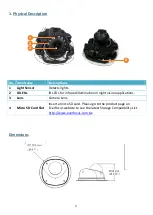
Optionally insert a micro SD card into the card slot (please refer to 

1. Physical 

Description

). 


8.


Access the web interface of IP camera (please refer to chapter 

4. Accessing the Camera

), 

and check if the camera is facing toward your desired direction. 
 

9.


To adjust camera viewing angles, loosen the screw to adjust the pan / tilt / rotate angles. 
You can optionally use the 

Angle Adjustment Tool

 to tilt and rotate the angle to your 

desired direction.   


Use Angle Adjustment Tool 

to tilt and rotate the angle


Summary of Contents for EMN2560

Page 1: ...cluding product pictures or screen shots in this document are for example only The images may vary depending on the product and software version Information contained in this document is subject to ch...

Page 2: ...ts lights 2 IR LEDs IR LEDs for infrared illumination in night vision applications 3 Lens Camera Lens 4 Micro SD Card Slot Insert a micro SD card Please go to the product page on EverFocus website to...

Page 3: ...Angle Adjustment Tool x 1 7 Desiccant Bag x 1 8 Hexagon Wrench x 1 9 Mounting Sticker x 1 10 Mounting Plate x 1 11 Quick Installation Guide x 1 Note 1 Equipment configurations and supplied accessorie...

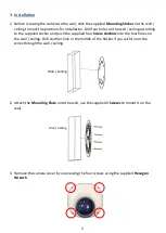
Page 4: ...supplied sticker and push the supplied four Screw Anchors into the four holes on the wall ceiling Drill another hole in the middle of the Sticker if you wish to run the wires through the wall ceiling...

Page 5: ...om the side cut b Use the supplied 2 Small Screws to lock the camera module to the Mounting Plate Camera Module Mounting Plate 5 Connect the camera to power You can either connect the camera to a 12VD...

Page 6: ...range Green with white stripe Blue Blue with white stripe Green Brown with white stripe Brown 7 Optionally insert a micro SD card into the card slot please refer to 1 Physical Description 8 Access the...

Page 7: ...tion capacity of the Desiccant Bag inside the camera body 11 Screw back the Camera Cover and the installation is complete 4 Accessing the Camera You can look up the IP address of the IP camera using t...

Reviews: