background image


6.


If the wires will be concealed, first connect the camera power and video (observe 

polarity for power – connecting reverse polarity will damage the camera and void the 

warranty. 

7.


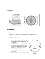
Attach the camera base to the mounting surface by 

passing the larger part of the ‘keyhole’ mounting 

holes over the heads of the screw and then twisting 

slightly clockwise. 

8.


While holding the base in the CW position, tighten 

the screws, being careful not to over tighten (and if 

wire is to be run along the mounting surface, be sure 

to pass the wire though the notch in the base). 


Adjusting the Camera Direction 


Rotate the inner mechanisms to point the camera in the desired direction. Rotate the camera 

module on its axis if necessary to align the image ‘upright’. Loosen the screws which lock the tilt 

mechanism.    Adjust to obtain the desired field of view and tighten the tilt mechanism screws.   


    Inner Mechanism                          Camera module 


Replace the dome cover removed in step 5 above, twisting the cover CW to lock it in place. 


CW 

Mounting Holes 

Tilt lock 

2 places 

Summary of Contents for EHD700

Page 1: ...ectromagnetic fields generated from these devices may distort the video image or otherwise interfere with camera operation 2 Never disassemble the camera beyond the recommendations in this manual nor...

Page 2: ...rface which will support the weight of the camera plus any wind snow ice or other loading and securely attach the camera to the mounting surface using screws and anchors which will properly support th...

Page 3: ...delivers exceptional low light sensitivity of 05 lux Automatic day night excellent low light sensitivity with switching from color to B W images at low levels of ambient light Back Light Compensation...

Page 4: ...mma Correction 0 45 Lens 3 6mm fixed Auto Gain Control Auto Electronic Shutter 1 60 1 50 1 100 000 sec Sync Mode Internal Day Night Auto Digital Day Night Digital Noise Reduction 2D DNR Adaptive Tone...

Page 5: ...d which is free of other electrical wires or other hazards 2 Place the drilling template on the ceiling or wall 3 Drill 2 or 3 holes 2 for mounting screws A B optionally 1 for power video cable if wir...

Page 6: ...s being careful not to over tighten and if wire is to be run along the mounting surface be sure to pass the wire though the notch in the base Adjusting the Camera Direction Rotate the inner mechanisms...

Page 7: ...21 Bandra Kurla Complex Bandra East Mumbai 400051 India TEL 91 22 6128 8700 FAX 91 22 6128 8705 www everfocus in UK Office Unit 12 Spitfire Business Park Hawker Road Croydon CR0 4WD London 0845 430 99...

Reviews: