EverFocus ECOR960 16F2 User Manual Download Page 19


ECOR960 4F2 / 8F2 / 16F2


10 

2.


Installation 

2.1


Hard Disk installation 

ECOR960 4F2/8F2: 

You can optionally install two 3.5” HDDs inside the ECOR960 8F2 DVR or one 3.5” HDD inside the 
ECOR960 4F2 DVR for recording videos. (The HDD installation instruction uses ECOR960 8F2 DVR 
as an example). 

1.


Make sure the DVR is power-off. 
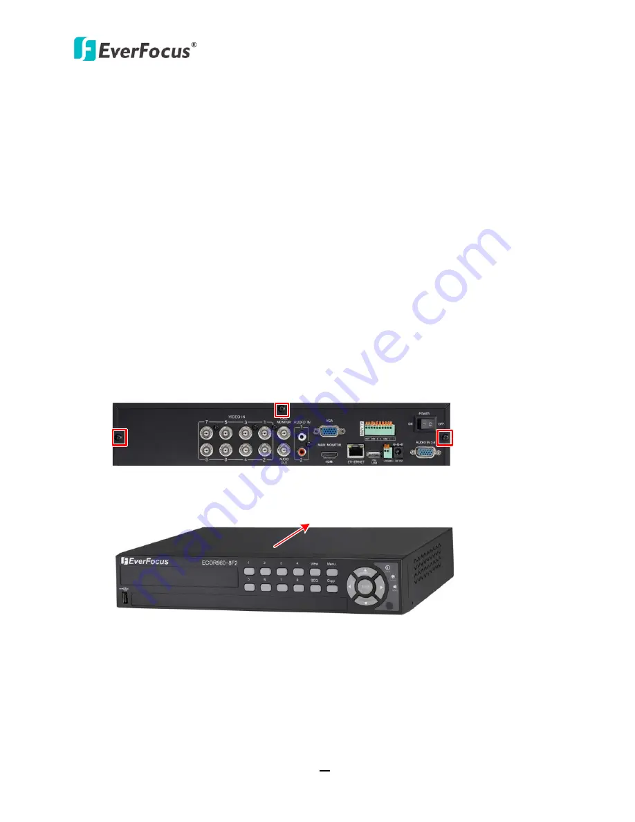
2.


Unscrew the three housing screws on the back panel of the DVR. 


Figure 2-1 

3.


Push the housing to the back and open it. 


Figure 2-2 


Chapter 

Summary of Contents for ECOR960 16F2

Page 1: ...ECOR960 4F2 8F2 16F2 DVR 4 8 16 CH H 264 960H User s Manual Copyright EverFocus Electronics Corp Release Date February 2014 Notice This content is subject to be changed without notice...

Page 2: ...he Everfocus Electronics Corporation Release Date February 2014 QuickTime is a registered trademark of the Apple Computer Inc Windows is a registered trademark of the Microsoft Corporation Linksys is...

Page 3: ...and refer servicing to qualified service personnel Moisture may damage the appliance and also may cause electric shock Do not use strong or abrasive detergents when cleaning the appliance body Use a d...

Page 4: ...ing to qualified service personnel Power Cord Protection Power supply cords should be routed so that they are not likely to be walked on or pinched by items placed upon or against them playing particu...

Page 5: ...connected Consult the dealer or an experienced radio TV technician for help FCC Caution Any changes or modifications not expressly approved by the party responsible for compliance could void the user...

Page 6: ...necting the DVR to the Network 22 2 5 1 Router or LAN Connection 22 2 5 2 Direct High Speed Connection 25 2 5 3 One to One Connection 26 3 Mouse and Front Panel Button Operation 30 3 1 USB Mouse Opera...

Page 7: ...for Playing Back 51 5 3 1 Time Search 51 5 3 2 Event Search 52 5 3 3 Smart Search 53 5 3 4 Snapshot Search 55 6 Configuration 57 6 1 Express 59 6 2 Camera 61 6 2 1 Basic Setting 61 6 2 1 1 Display Asp...

Page 8: ...tem 109 6 10 2 Log 110 7 Remote Access to the DVR 111 7 1 Accessing the DVR on the Network 111 7 2 Install JAVA Runtime 113 7 3 Browser Security Setting 115 7 3 1 Installing ActiveX Controls 115 7 3 2...

Page 9: ...sers to change the Recording Format from WD1 to D1 mode NTSC 704X480 704X240 352X240 PAL 704X576 704X288 352X288 if needed To select the desired Recording Format please see 6 6 1 Monitor OSD Before sw...

Page 10: ...MI and VGA monitors with an intuitive onscreen user interface for efficient operation User can also easily operate the machine using a USB mouse or via the front panel buttons When paired with our pow...

Page 11: ...n Monitor HDMI Call Monitor BNC Web Remote Client PowerVideo Plus CMS Mouse or USB Memory Stick Line Level Audio Out Main Monitor VGA Power Supply RS 485 Device Line Level Audio In 3 8 Audio Cable Mou...

Page 12: ...onal Analog Camera Line Level Audio Out Line Level Audio In Alarm In Out Main Monitor HDMI Call Monitor BNC Web Remote Client PowerVideo Plus CMS Mouse USB Memory Stick Line Level Audio Out Main Monit...

Page 13: ...ble remote access Supports live monitoring and playback of video from mobile devices via Mobile applications MobileFocus MobileFocus Plus Multiple Control Inputs Mouse front panel remote controller Mu...

Page 14: ...rocess 3 Two SATA cables will be supplied for DVRs without HDDs installed If the order contains HDD installation the SATA cable will not be supplied 4 Risk of explosion if battery is replaced by an in...

Page 15: ...ECOR960 4F2 8F2 16F2 6 1 4 Front Panel ECOR960 4F2 1 2 4 5 6 7 8 9 10 11 12 3 ECOR960 8F2 3 6 2 11 10 12 1 8 9 ECOR960 16F2 3 6 13 11 10 12 1 8 9 Figure 1 3...

Page 16: ...ress to enter the Copy Menu 7 Zoom Press repeatedly to toggle between 2x and 4x zoom Press the Menu button to switch zoom off 8 Arrow Keys Use these arrow keys to change the Menu settings 9 IR Receive...

Page 17: ...ECOR960 4F2 8F2 16F2 8 1 5 Rear Panel ECOR960 4F2 2 3 1 4 5 6 7 8 9 10 11 12 13 ECOR960 8F2 2 3 1 4 5 6 7 8 9 10 11 12 13 ECOR960 16F2 2 3 1 13 5 6 7 8 4 9 10 11 12 Figure 1 4...

Page 18: ...8F2 Audio Output RCA 16F2 If it is a BNC connector please connects to the audio output devices such as speakers using the supplied BNC to RCA Connector Note that the speaker with a built in amplifier...

Page 19: ...de the ECOR960 8F2 DVR or one 3 5 HDD inside the ECOR960 4F2 DVR for recording videos The HDD installation instruction uses ECOR960 8F2 DVR as an example 1 Make sure the DVR is power off 2 Unscrew the...

Page 20: ...VR using supplied screws 8CH DVR Figure 2 3 5 Connect the internal SATA cable to the SATA port of the HDD Figure 2 4 6 Connect the internal power cable to the HDD Figure 2 5 7 Screw back the hosing to...

Page 21: ...VR 1 Follow the above same step 1 3 to open the housing of the ECOR960 16F2 Figure 2 6 2 The HDDs have to be mounted upside down with the connectors facing inwards so please slide the HDD under the HD...

Page 22: ...the other HDD Figure 2 9 5 Connect the internal SATA cable to the SATA port of the HDD and the internal power cable to the HDD as the Figure 2 4 and Figure 2 5 Figure 2 10 6 Screw back the hosing to t...

Page 23: ...00NM0033 4TB Constellation CS SED SATA3 ST3000NC000 3TB CE Video SATA3 ST3500312CS 500GB CE Video SATA3 ST1000VM002 1TB CE Video SATA3 ST2000VM003 2TB CE Video SATA3 ST3000VM002 3TB CE Video SATA3 ST4...

Page 24: ...ces such as microphones are required to have a built in amplifier and external power supply Please refer to 1 5 Rear Panel 3 Using the supplied Power Cord connect one end to the DC 12V port on the DVR...

Page 25: ...8 KHz hor Make sure that the connected monitor s specifications comply with these resolution requirements This figure uses ECOR960 16F2 DVR as an example Main Monitor Call Monitor Main Monitor BNC Cab...

Page 26: ...No Description 1 4 ALM_IN1 ALM_IN4 G GND Alarm Input Contacts This DVR provides one alarm input per camera All inputs are programmable N O Normal Open or N C Normal Closed All settings are programmed...

Page 27: ...been installed properly Once you have completed the basic cable connections you are ready to turn on the DVR To turn on the power connect the supplied Power Cord to the power outlet and turn on the P...

Page 28: ...ls cfm Please connect the DVR in the same LAN of your computer 1 Install and then start the IPU program The following dialog box appears Figure 2 16 2 IPU will automatically search the IP devices conn...

Page 29: ...n option Click Set IP Address to save the settings Figure 2 18 Note Most networks uses DHCP to assign IP address if you are unsure of your network settings please consult your network administrators f...

Page 30: ...ActiveX Controls 10 You may need to turn User Account Control off if you still can t see the Remote Live View 11 On the computer click Start Control Panel System and Security Action Center click Chang...

Page 31: ...ted to a router and allows multiple users on and off site to see the DVR on a LAN WAN Internet The DVR must be assigned an IP address that is compatible with its LAN By setting up port forwarding on t...

Page 32: ...Menu To let the router automatically assign an address Set the Network Type to DHCP Make sure to write down the IP address and the Gateway Exit from the Menu to save settings To manually assign an ad...

Page 33: ...hin your router Log into the router using a PC and open the following ports Ports to open 80 If your Internet service provider blocks port 80 you can change it to a different port in the DVR s Network...

Page 34: ...se a cross over network cable for this application Once you have a straight through cable plug one end into the LAN port on the back of the recorder and the other into the high speed modem Log into th...

Page 35: ...le Please remember you can not use a straight through network cable for this application Once you have a cross over cable plug one end into the LAN port on the back of the DVR and the other into the n...

Page 36: ...ECOR960 4F2 8F2 16F2 27 Go to Start Double click on Control Panel Figure 2 25 Click Network and Sharing Center Figure 2 26 Click Local Area Connection Figure 2 27...

Page 37: ...ECOR960 4F2 8F2 16F2 28 Click Properties Figure 2 28 Click on Internet Protocol Version 4 TCP IPv4 and then click Properties Figure 2 29...

Page 38: ...address of 192 168 1 2 a Subnet Mask of 255 255 255 0 and a Default Gateway of 192 168 1 1 and then click OK Figure 2 30 Restart both of the computer and the DVR To access the DVR from the computer si...

Page 39: ...to Select a Channel Enable Audio 1 In the Live View window you can select a channel by clicking once on the desired channel screen The selected screen will be highlighted by a red frame 2 Double clic...

Page 40: ...er The buttons on the right and bottom have the following functions Drop Down Box Click on the down arrow to see all selections then directly click on an option to select it Check Box Click on the box...

Page 41: ...ow keys to scroll through each channel The selected channel will be highlighted with a white frame 2 After selecting a channel press the Enter button to turn On Off the Audio function An Audio icon wi...

Page 42: ...tton to enable it checked or disable it unchecked Button Press the Enter button to execute the function Bar Press the Enter button to activate the slider press the right and left arrow keys to adjust...

Page 43: ...en the Login window appears Figure 3 3 2 The default user name and password are User admin Password 11111111 Note For details on setting up multiple user accounts please refer to 6 9 4 User Management...

Page 44: ...select a camera follow the instructions below Using a mouse Click a camera on the screen and the selected camera will be highlighted with a red frame All cameras will be selected when you scrolling th...

Page 45: ...ere are four audio input devices Figure 3 5 Note that the DVR only provide one channel audio output You can switch the Audio Output function to either one from the cameras To switch the Audio Output f...

Page 46: ...ing videos For details please refer to 5 Search and Playback 2 PTZ Click to display the PTZ Control Panel for controlling the connected PTZ cameras For details please refer to 4 1 PTZ 3 Layout Click t...

Page 47: ...e Main Monitor click the button Note that the Call Monitor can only be used to display camera views The functions including the layout channel switching icon display sequencing mode of the Call Monito...

Page 48: ...e PTZ Control Panel 1 To move the camera to the desired direction and angle click the Direction buttons 2 To zoom in out the camera view click the Zoom buttons 3 To adjust the camera focus click the F...

Page 49: ...ber c Click the Go button 12 To remove a pre configured Tour if supported by the camera a Click the Tour button b Click the desired Tour number c Click the Delete button Click C to clear the entered n...

Page 50: ...s and zoom by clicking directly on the screen Figure 4 3 Direction Controls When your mouse cursor turns into a direction icon click on the screen will force the camera to turn in that direction Focus...

Page 51: ...tton on the front panel of the DVR to switch to a desired layout To display a channel in full screen press the channel buttons on the front panel 4 3 Channel Switching You can switch the selected came...

Page 52: ...e are four display modes and you can click the Display button to change the display mode 1 Display both the camera and system status icons 2 Display only the camera status icons 3 Display only the sys...

Page 53: ...isplayed on the top screen 2 Navigate the camera view to the desired position by moving your mouse cursor over the camera view The mouse cursor will turn into a direction icon when you move your mouse...

Page 54: ...dings of selected cameras from main stream or sub stream Player Check the box to include the EFPlayer program in the copy You can use the EFPlayer on a computer to play back the recordings Start Date...

Page 55: ...ow as Figure 4 9 Press Yes when you are ready to logout of the system You will need to login again before accessing the OSD Root Menu Figure 4 9 If you do not need the Login Logout step before enterin...

Page 56: ...o enable the Temporarily Logout function follow the steps below Ensure the User Login box is Unchecked Figure 4 10 1 Select the cameras to be hidden once enabling the Temporarily Logout function and t...

Page 57: ...layback box in the Express setting page OSD Root Menu System Express to enable the configured time in the field below 2 Enter the desired time for playing back the recording Take 60 seconds for exampl...

Page 58: ...d Alarm Event 3 Playback Speed Indicates the current Playback Speed up to 8X 4 Express Copy Click to bring up the Copy menu for archiving the recordings log data to the USB storage device For details...

Page 59: ...0 days L2 Entire Time Bar scale is 2 weeks L3 Entire Time Bar scale is 1 week L4 Entire Time Bar scale is 1 day L5 Entire Time Bar scale is 1 hour L6 entire Time Bar scale is 30 minutes 13 Time Bar Sc...

Page 60: ...or Snapshot Search to enter to the setup menu To bring up the Search menu By Mouse Right click to bring up the OSD Root Menu and then click the Search button By Front Panel Press the Search button EC...

Page 61: ...lick to bring up the on screen clock to select the start end time Camera Select the desired cameras to be searched Event Select an event type to be searched Search Click to start searching The search...

Page 62: ...tting Click to set up the motion areas The Motion Grid Setup menu appears Search Click to start searching The search results will be listed in the Event List menu see Figure 5 6 To set up the Motion G...

Page 63: ...Click to select the entire area Clear All Click to clear all the selected areas Save and Back Click to save the configured motion areas and return to the Smart Search menu Cancel Click to cancel all c...

Page 64: ...on screen clock to select time Search Direction Click to search forward backward based on the setup time above Search Camera Select a desired camera to be searched Result Interval Click to set up the...

Page 65: ...10 2 Right click on the screen the Resume Playback Bar appears in the middle of the screen Previous Play Close Next Figure 5 11 3 Click the Previous or Next buttons to display the previous next snaps...

Page 66: ...ontrol or the optional device EKB500 keyboard The following operations are examples of using a Mouse This chapter describes the functions and options of the Configuration Setting in the on screen disp...

Page 67: ...r 6 5 Hard Disk 6 5 1 Disk 6 5 2 Lock Format 6 6 Display Setting 6 6 1 Monitor OSD 6 6 2 M T SEQ 6 7 Network 6 7 1 LAN 6 7 2 Email 6 7 3 DDNS 6 7 4 FTP 6 7 5 Alarm Server 6 7 6 Network Test 6 8 Schedu...

Page 68: ...ord Mode Select a recording mode from the drop down list Blank Select this option for all cameras to keep the current individual record settings without any changes Please refer to 6 8 1 Express Setup...

Page 69: ...ting page please refer to 6 6 1 Monitor OSD to select either NTSC or PAL in the TV Format drop down list Record With Select a record method Blank Select this option for all cameras to keep the current...

Page 70: ...itle supports up to 16 characters Install Check the box to enable the selected camera Covert Check the box to hide the camera stream in Live View and Sequence modes However the DVR will still record t...

Page 71: ...and Sub Stream The options include Low Basic Standard High and Superior The higher the quality the more the HDD space is used Normal Speed Select a frame rate per second FPS for continuous recording T...

Page 72: ...o also change the camera live view display to 16 9 aspect ratio in the Ratio drop down list see 6 2 1 Basic Setting Screen Mode 1920x1080 16 9 Camera Ratio 16 9 Camera Ratio 4 3 Figure 6 4 If selectin...

Page 73: ...the selected camera Figure 6 6 Camera Select a camera to adjust the following settings Brightness Move the bar to adjust the brightness Contrast Move the bar to adjust the contrast Color Move the bar...

Page 74: ...Schedule Setting for more details Record Status Relay Output Select a number to monitor the recording status of the selected alarm relay The recording status of the selected alarm relay will be transm...

Page 75: ...that the pre alarm recording rate will follow the Normal Speed configured in the earlier section see 6 2 1 Basic Setting Buzzer Check the box to enable the buzzer when an alarm event is triggered Ema...

Page 76: ...econds Timeout Duration This function only appears when you select Timeout or Trans Timeout options in the Output Type drop down list Select a duration time for the motion event The alarm output will...

Page 77: ...the Normal Speed configured in the above section see 6 2 1 Basic Setting Buzzer Check the box to enable the buzzer when a video loss event is triggered Email Notify Check the box to send email notific...

Page 78: ...resets the alarm remotely Transparent Alarm output remains as long as the alarm input is active Trans Timeout Alarm output continues until event ends then continues for the setup duration time 10 150...

Page 79: ...section see 6 2 1 Basic Setting Buzzer Check the box to enable the buzzer when a motion event is triggered Email Notify Check the box to send email notification when a motion event is detected Email...

Page 80: ...put is active Trans Timeout Alarm output continues until event ends then continues for the setup duration time 10 150 seconds Timeout Duration This function only appears when you select Timeout or Tra...

Page 81: ...rea drag a rectangle with your mouse from bottom to top lower right to upper left 5 Follow Step 3 to set up multiple motion areas if necessary 6 Sets up the Sensitivity Min Area and Motion Delay for t...

Page 82: ...entered in the Email setup menu see 6 7 2 Email Network Alarm Check the box to send out a network alarm to a client PC This feature works with EverFocus CMS software You will need to configure the Al...

Page 83: ...l Network Alarm Check the box to send out a network alarm to a client PC when HD fails This feature works with EverFocus CMS software You will need to configure the Alarm Server for the DVR to send ne...

Page 84: ...en an alarm is triggered the signal will be transmitted through the selected alarm output relay Output Type Select an output type when HD is full Timeout Select this option and then set up the Timeout...

Page 85: ...be transmitted through the selected alarm output relay Output Type Select an output type when HD is off Timeout Select this option and then set up the Timeout Duration in the field below the alarm out...

Page 86: ...tup menu see 6 7 2 Email Network Alarm Check the box to send out a network alarm to a client PC when power has been restored This feature works with EverFocus CMS software You will need to configure t...

Page 87: ...will remain active until the user presses the Enter key on the IR Remote Control or resets the alarm remotely Transparent Alarm output remains as long as the alarm input is active Trans Timeout Alarm...

Page 88: ...Time Start Shows the earliest recording time of the DVR Record Time End Shows the latest or most current time on the DVR Disk Select a disk number Health Status Displays the current status of the sele...

Page 89: ...4 1 Alarm Current Lock Displays the current percentage of the locked event recordings in the hard disk If the amount of locked event recordings has reached the maximum lock percentage the DVR will be...

Page 90: ...display hard drive status only for main monitor Playback Date Time Check the box to display playback date time only for main monitor Playback Status Check the box to display playback status only for...

Page 91: ...4x288 352x288 PAL Please go to Basic Setting page see 6 2 1 Basic Setting to select the desired resolution for live view recording 6 6 2 M T SEQ You can configure up to 20 steps of the sequencing orde...

Page 92: ...igure an IP address to the DVR Figure 6 22 Network Type Three options are selectable Static IP DHCP and PPPoE Static IP User can set a fixed IP for network connection DHCP DHCP server in LAN will auto...

Page 93: ...your DVR locally and or remotely It is strongly recommended that you assign a fixed static IP address to your DVR and that in order to avoid address conflicts the IP address assigned be outside of the...

Page 94: ...routers However if you desire remote access to your DVR perhaps using DDNS optional you MUST select functional ports and set up the port forwarding in your router Other ports such as 8080 and 8000 are...

Page 95: ...unication to be encrypted by SSL User Name Input the login user name if the SMTP server requires authentication Password Input the password if the SMTP server requires authentication Confirm Input the...

Page 96: ...trouble of checking if the IP address assigned by DHCP Server has changed Once the IP is changed the DVR will automatically update the information to the DDNS to ensure it is always available for remo...

Page 97: ...Input the desired name for the DVR Note that the name of the DVR cannot include a space or a dot period or any special characters particularly Note 1 It is not necessary to append the HTTP port numbe...

Page 98: ...org from the DDNS Service drop down list 4 Enter the host name in the Host Name field Note that the name of the DVR cannot include a space or a dot period or any special characters particularly _ 5 En...

Page 99: ...ings or snapshots please see 6 4 1 Alarm and 6 4 3 Motion Figure 6 27 FTP Server Enter the IP address or the host name of the FTP server Port Enter the port number for the FTP server Default is 21 Use...

Page 100: ...itted to up to 3 addresses Protocol Select the protocol type for alarm transmission Note the protocol selected here should match the protocol set up for the CMS alarm server UDP User Datagram Protocol...

Page 101: ...vity problems by obtaining responses from nodes progressively farther along the network DNS functionality can also be confirmed by entering a valid DNS name instead of an IP address Figure 6 29 To ver...

Page 102: ...Daytime End Select a weekday end time Nighttime schedule ends when Daytime ends Record Type Select a recording type for each time period Disable No recording during the scheduled time period Normal Ev...

Page 103: ...r the selected group above Disabled Select to disable the Holiday Others recording schedule One time Select this option and then set up the specific date and year in the Details field The DVR will sta...

Page 104: ...time block for Holiday Hol Other Oth Sunday Sun Monday Mon Tuesday Tue Wednesday Wed Thursday Thu Friday Fri or Saturday Sat Time 0 23 The numbers represent the 24 hours of a day Time Bar The time bar...

Page 105: ...six record modes on each time bar Click the Edit Timezone button to edit the recording parameters for a time zone Figure 6 33 Editing Timezone From Displays time zone start time To Displays time zone...

Page 106: ...ivided across the cameras responding to an event Action Check this box to enable notifications enabled elsewhere Buzzer Alarm out E mail and Network Alarm when an event occurs Apply to Days This butto...

Page 107: ...the DVR to adjust to when updating from the time server NTP Select Disable Enable for NTP time synchronization NTP Server Displays the time server address that the DVR uses for time synchronization R...

Page 108: ...hh mm Set the time when daylight saving time begins Set To hh mm This is what the time will change to when daylight saving begins For most regions this will be one hour ahead of the Start Time End Da...

Page 109: ...9 4 User Management For example if this box under the Operator level has been checked any user with the Operator privilege can go to the User Management setting page to set up the settings of other Op...

Page 110: ...ccount to a new user account Edit Click the button to edit the settings of an existing user account Add Click the button to add a new user Delete Click the button to delete Login Check the box to enab...

Page 111: ...p the keyboard and input the desired user name User Group Select a user group access level Status Select to enable or disable the user account Password Input the password Confirm Enter the same passwo...

Page 112: ...ECOR960 4F2 8F2 16F2 103 Figure 6 41...

Page 113: ...ansmit instruction or information through the RS 485 port on the DVR There are eight different speeds 1200 BPS 2400 BPS 4800 BPS 9600 BPS 19200 BPS 38400 BPS 57600 BPS and 115200 BPS Data Bit This fie...

Page 114: ...including Preset Position Auto Pan Tour and Pattern please refer to 4 1 PTZ Camera Figure 6 43 The control keys on the EKB200 Figure 6 44 After connecting the EKB200 keyboard to the DVR and configurin...

Page 115: ...ue column Tour Stop Press this key to stop running the Tour number specified in the Value column Pattern Run Press this key to start running the Pattern number specified in the Value column Pattern St...

Page 116: ...e Click to upgrade the latest firmware Note you will need to restore the firmware file to the USB flash device and then connect the USB flash device to the DVR Configurations Load Factory Default Clic...

Page 117: ...te Reboot Check the box to enable restarting the DVR via the Network Figure 6 46 Shutdown Press the Shutdown button if you need to turn off the DVR When the message as below pops up on the screen you...

Page 118: ...NTSC PAL Displays the current video format automatically detected by the DVR S N Display the serial number of the DVR Lan IP 1 Displays the IP address of LAN 1 set up in the Network or Express menu MA...

Page 119: ...d to set up the start end date Start Time End Time Click to bring up the on screen clock to set up the start end time Log Type Select the desired log types View Log Click to bring up the Log List show...

Page 120: ...Local connection http IP address from the DVR s Network Menu IP port used e g http 192 168 1 163 2468 Internet connection http IP address given by your Internet Service Provider IP port used e g http...

Page 121: ...r Please check the Always trust content from this publisher box and click the Run button to run the EverFocus Viewer application Figure 7 2 6 You may need to turn User Account Control off if you still...

Page 122: ...Update to go to the JAVA website http www java com en and download the latest version of the JAVA software 3 Please go to the Control Panel JAVA Control Panel to change settings 4 If you can t find t...

Page 123: ...e Status Protocol OCSP Also check Place JAVA icon in system tray in Miscellaneous option Figure 7 6 7 Scroll to Default JAVA for Browser and check Mozilla family Figure 7 7 8 Connect the DVR s IP addr...

Page 124: ...be too high If so go to Section 7 3 2 Enabling ActiveX Controls 1 You may also prompt to install the MSXML file Please right click the yellow bar and select Run Add on Figure 7 8 2 Install the MSXML...

Page 125: ...essary if you DO NOT see the image Figure 7 8 popping up when you first connect to the DVR 1 At the top of the Internet Explorer Window click on Tools and then select Internet Options Figure 7 11 2 Cl...

Page 126: ...orer 7 only Allow scriptlets IE7 only Automatic prompting for ActiveX controls Binary and script behaviors Display video and animation on a webpage that does not use external media player IE7 only Run...

Page 127: ...gin screen 6 Click the Refresh button to reload the page Figure 7 14 7 You may need to run the EverFocusViewer application when prompted to do so Figure 7 15 8 The login page will show up Type in the...

Page 128: ...Speaker button to transfer audio to the client side from DVR if there is a speaker on the PC and a microphone and preamp attached to the DVR and audio recording is enabled on the DVR Click the Microph...

Page 129: ...ream White Indicates the live view is in a normal status Orange Indicates a motion is being detected Blue Indicates video loss Red Indicates an alarm event is triggered Grey Indicates the live view is...

Page 130: ...ings for displaying the camera information on the camera live view Please refer to 6 6 Display Settings 8 Network Click to configure the network settings Please refer to 6 7 Network Settings 9 Schedul...

Page 131: ...ime Search Event Search or Smart Search and then set up the settings For more details about Search setting please refer to 5 3 Searching the Recordings for Playing Back Double click on a recording the...

Page 132: ...64 Video Format NTSC PAL Video Inputs 16 x BNC 8 x BNC 4 x BNC Video Outputs Main Main HDMI and VGA Call BNC Recording Frame Rate per Channel at Resolution NTSC PAL 30 25 fps ch at 960x480 WD1 30 25 f...

Page 133: ...F 104 F 20 80 humidity Dimensions W x D x H 320 x 267 8 x 59 9mm 12 6 x 10 54 x 2 36 Weight without HDDs 6 0 kgs 13 23 lbs 3 14 kgs 6 92 lbs 2 36 kgs 5 2 lbs Language English Japanese Traditional Chi...

Page 134: ...wer is on Verify the recorder is getting the correct supply power There is no display coming from one of the channels on the DVR In the DVR s Camera Menu make sure that all cameras are checked as Inst...

Page 135: ...r on the LAN For example one computer on a network could have an IP address of 192 168 1 127 You should never give two or more devices the same exact IP address but the first three octets of an IP add...

Page 136: ...rs at the lower end of the range such as 80 for HTTP Ports are similar to doors and windows of your house with port 80 acting as the front door If these are not open you could not enter the house This...

Page 137: ...tatic IP address ______________ A Static IP address means you use the same IP address every time you connect to the Internet With a static IP address other Internet users always know the address of yo...

Page 138: ...ke a direct connection from one computer to another or in this case a computer to a DVR Direct High Speed Modem Connection A direct modem connection uses a standard network cable to connect the modem...

Page 139: ...ccess the Web based Utility launch a web browser and type the Router s IP address typically 192 168 1 1 in the address bar Then press Enter A password request page will appear Non Windows XP users wil...

Page 140: ...g number of the range under Start and the ending number under End Protocol Enter the protocol used for this application either TCP or UDP or Both IP Address For each application enter the IP Address o...

Page 141: ...on it If you need additional technical support on this router you must call D Link Whenever you want to configure your network or the DI 624 you can access the Configuration Menu by opening a web bro...

Page 142: ...The port number that the service uses on the LAN Local Area Network Public Port The port number that the services uses on the WAN Wide Area Network Schedule The time period the virtual server will be...

Page 143: ...his alarm mode related to event record alarm outputs OSD message buzzer Timeout Transparent Mode t Input Event Alarm Duration t Duration t Reaction t Event t Event Duration of alarm input source motio...

Page 144: ...reaction Resulting duration for this alarm mode related to event record alarm outputs OSD message buzzer Permanent Mode t Input Event Alarm Duration t Reaction t Event Alarm Reset t Event Duration of...

Page 145: ...t reaction Resulting duration for this alarm mode related to event record alarm outputs OSD message buzzer Timeout Transparent Mode Retrigger of Alarms t Event Duration of alarm input source motion co...

Page 146: ...use set 8 Checking Order 1 2 3 4 5 6 7 8 Normal Frame Rate 1 1 1 1 1 1 1 1 Quality Superior Standard Low Low Low Low Low Low Event Frame Rate 30 30 30 15 10 7 5 5 1 Case 2 Record Mode Event Only Reco...

Page 147: ...ccording to the Preset Settings Preset Setting Option Camera Item Apply value Best Quality Quality Superior Normal Frame Rate Max recording frame rate of DVR Event Frame Rate 30 Standard Quality Quali...

Page 148: ...from the Remote Control To select the DVR ID 1 Aim at the IR receiver of your DVR 2 Press the DVR Device Button 3 Select the DVR ID number by pressing the Number Button The DVR ID number here must co...

Page 149: ...icho City Building 2 13 4 Koto Bashi Sumida Ku Tokyo 130 0022 Japan TEL 81 3 5625 8188 FAX 81 3 5625 8189 www everfocus co jp info everfocus co jp EverFocus India Suite 803 Housefin Bhavan C 21 Bandra...

Reviews: