background image


EBD431e


4

3.


INSTALLATION


&


OPERATION


1.


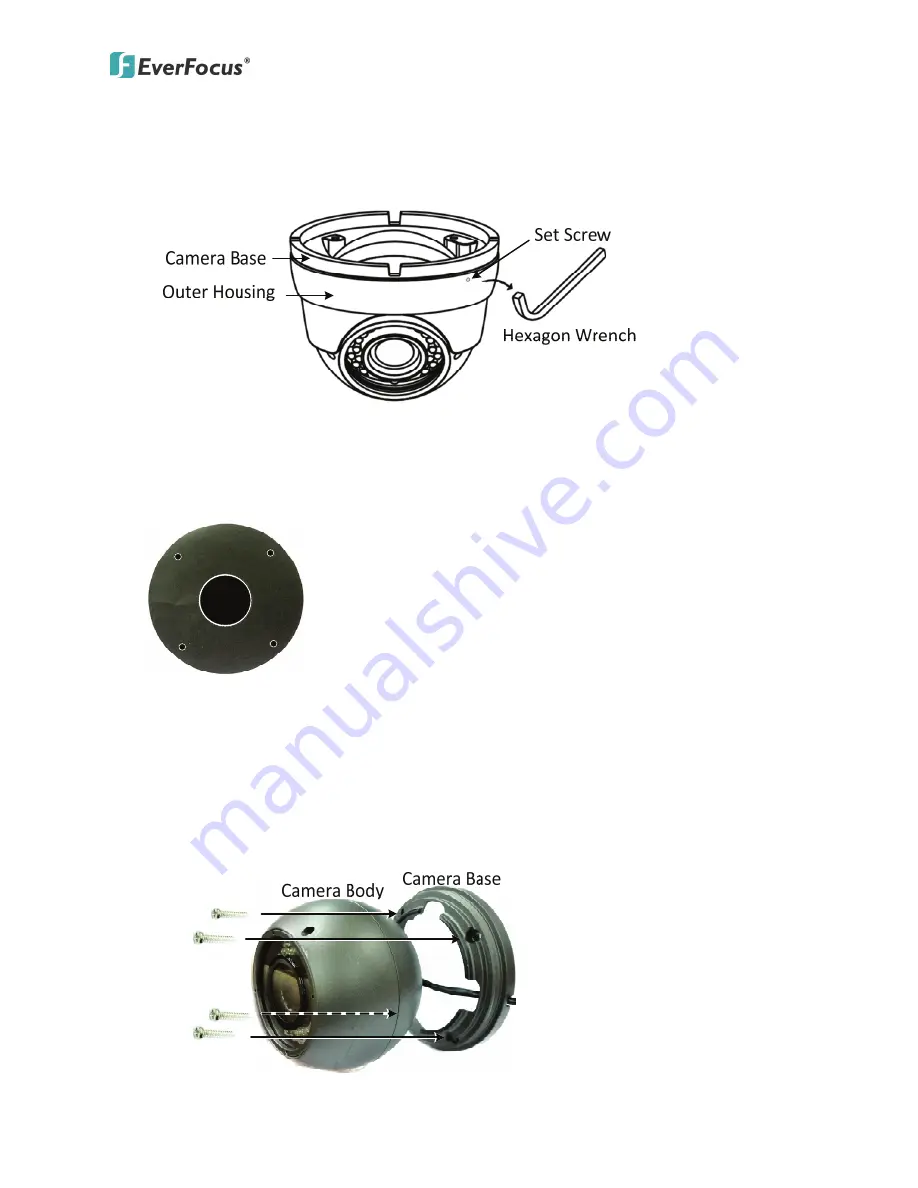
Unscrew


the


Set


Screw


using


the


supplied


Hexagon


Wrench


and


then


remove


the


Outer


Housing


from


the


Camera


Base.


2.


Paste


the


supplied


mounting


template


onto


a


desired


location


on


the


ceiling


/


wall.


Drill


the


four


small


holes


for


screwing


the


camera


with


the


supplied


Screws


and


Anchors,


and


the


circle


in


the


middle


only


if


you


wish


to


run


the


wires


into


the


wall.


3.


Insert


the


supplied


4


Anchors


into


the


4


holes


on


the


ceiling


/


wall.


4.


Screw


the


Camera


Base


to


the


ceiling


/


wall


using


the


supplied


4


Screws.


a.


If


you


want


to


wire


the


cables


from


the


side


cut


of


the


Camera


Base,


run


the


cables


through


the


Camera


Base


first,


attach


and


then


screw


the


Camera


Base


to


the


ceiling


/


wall.


Summary of Contents for EBD431e

Page 1: ...EBD431e Indoor Outdoor Ball Camera 700TVL 3 Axis IP66 IR User s Manual Copyright EverFocus Electronics Corp Release Date August 2012...

Page 2: ...y from water and other liquids and never touch the power cord with wet hands 5 Never install the camera in areas exposed to oil gas or solvents 6 Do not operate the camera beyond the specified tempera...

Page 3: ...e for outdoor use Model Name Scanning System EBD431e N NTSC EBD431e P PAL Note The models vary among countries Please visit EverFocus regional Websites for detailed ordering information 1 1 FEATURES 3...

Page 4: ...e Name Description Power Cable Connects to the 12V DC power source You can optionally use the supplied Power Adapter Pigtail or a power adapter Video Out Cable BNC Connects to a DVR or a portable moni...

Page 5: ...s Type Varifocal Lens f 2 8 10 5mm F 1 2 Auto Gain Control Yes White Balance Auto Sync Mode Internal Sync True Day Night Yes True Day Night auto switch DNR Yes D WDR Auto Sony ATR IR LED 36 Units IR L...

Page 6: ...es for screwing the camera with the supplied Screws and Anchors and the circle in the middle only if you wish to run the wires into the wall 3 Insert the supplied 4 Anchors into the 4 holes on the cei...

Page 7: ...using the supplied Power Adapter Pigtail or a power adapter 6 Connect the camera to a DVR or a portable monitor using the Video Out cable for viewing the camera view while adjusting camera focus zoom...

Page 8: ...nu items Push the Joystick left right to adjust the level of the selected item Press the Joystick to enter the submenu or exit the OSD Setup Menu 4 2 OSD Setup Menu OSD Setup Menu page 1 LENS SHUTTER...

Page 9: ...IS AUTO IRIS SHUT BRIGHTNESS 000 255 LOW LUMINANCE MODE AGC OFF BRIGHTNESS x0 25 x0 50 x0 75 x1 00 MANUAL MODE SHUT AUTO IRIS Exposure is controlled by auto electronic shutter combined with auto iris...

Page 10: ...onment Range Setup PUSH The function will keep on detecting the Color Temperature and then keeps saving up the parameter to the camera USER1 USER1 B GAIN 000 255 R GAIN 000 255 USER2 USER2 B GAIN 000...

Page 11: ...TR function ON LUMINANCE LOW MID HIGH CONTRAST LOW MIDLOW MID MIDHIGH HIGH Note Please avoid enabling the ATR and Backlight functions simultaneously 4 2 6 NR Noise Reduction NR MODE Y C Y C OFF Y LEVE...

Page 12: ...0 255 NIGHT DAY 000 255 BURST Selects whether to output the burst signal when under Night status has been identified DELAY CNT Set the Night Day identification transfer time Default 4Sec DAY NIGHT Set...

Page 13: ...tion ON AREA SEL Max 8 TOP 000 244 NTSC 000 288 PAL BOTTOM 000 244 NTSC 000 288 PAL LEFT 600TVL 000 378 NTSC 000 370 PAL 700TVL 000 474 NTSC 000 468 PAL RIGHT 600TVL 000 378 NTSC 000 370 PAL 700TVL 00...

Page 14: ...370 PAL 700TVL 000 474 NTSC 000 468 PAL RIGHT 600TVL 000 378 NTSC 000 370 PAL 700TVL 000 474 NTSC 000 468 PAL DETECT SENSE Set the motion detection sensitivity BLOCK DISP Control the ON OFF status of...

Page 15: ...creen when the Enter operation input is performed from the status in which POS has been selected using the character selection cursor On the camera ID display position setting screen the camera ID dis...

Page 16: ...5625 8189 www everfocus co jp info everfocus co jp EverFocus Europe UK Unit 12 Spitfire Business Park Hawker Road Croydon Surrey CR0 4WD UK TEL 44 20 8649 9757 44 845 430 9999 FAX 44 20 8649 9907 www...

Reviews: