background image

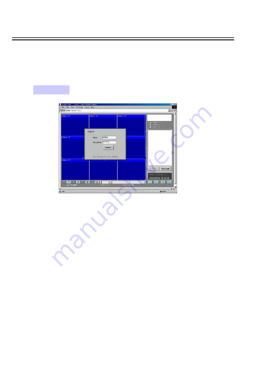
12. View From Internet/Intranet

Basic Operations and Login Display:

Go to the Internet Explorer, key in the network IP address, for example,

http://192.168.10.5

(must be the same IP address as the one assigned to the 

unit from the Network Setting Menu. You need a FIXED IP Address, please contact your ISP for the IP)

The LOGIN dialog will show on the screen.
User’must enter the correct user-name and password defined in the Network Setting menu.

For example:
Enter ADMIN for user name and ADMIN for password and then Click On “submit”to enter to system. 

38

View From Internet/Intranet

Summary of Contents for DVR-1600

Page 1: ...INSTRUCTION MANUAL DVR 900 9 Channel Duplex Digital Video Recorder V1 02 DVR 1600 16 Channel Duplex Digital Video Recorder ...

Page 2: ... and refer servicing to qualified service personnel Moisture may damage the appliance and also cause electric shock Do not use strong or abrasive detergents when cleaning the appliance body Use a dry cloth to clean the appliance when it is dirty When the dirt is hard to remove use a mild detergent and wipe gently Do not overload outlets and extension cords as this may result in a risk of fire or e...

Page 3: ...t and should be handled carefully Check to ensure that the following items are included 1 Digital Video Recorder unit 2 User s manual 3 Power Cord 4 HDD tray key and screws 5 Alarm I O board If an item appears to have been damaged in shipment replace it properly in its carton and notify the shipper Safety Precautions Do not place on uneven or unstable work surfaces Seek servicing if the casing Pow...

Page 4: ... a bath tub wash bowl kitchen sink or laundry tub in a wet basement near a swimming pool in an unprotected outdoor installation or any area which is classified as a wet location Servicing Do not attempt to service this unit yourself as opening or removing covers may expose you to dangerous voltage or other hazards Refer all servicing to qualified service personnel Power Cord Protection Power suppl...

Page 5: ...g menu 23 6 13 Matrix setting menu 24 6 14 System setting menu 25 7 Recording 26 7 1 Instant recording 26 7 2 Alarm recording 26 8 Playing back 27 8 1 Normal playback 27 8 2 Search playback 28 30 9 Copy 31 9 1 Still image copy 31 9 2 Copy to movie file 32 9 3 Export event log list 33 10 Monitor Views Operation 34 10 1 Main monitor 34 10 2 Call Matrix monitors 35 11 Remote Control 36 11 1 RS 485 re...

Page 6: ... demand 1 1 Main Features Product Overview Easy to use control panel with common VCR and Multiplexer functions Shuttle Jog dial for picture by picture or fast slow viewing No tapes to manage clean or replace Instant retrieval of stored video On screen setup menu and system timer Ethernet TCP IP connectivity for remote viewing and controlling Pre Alarm recording Built in M JPEG compression decompre...

Page 7: ...r Schedule Alarm or Motion Recording Recording Mode Two 3 5 IDE type hot swappable Hard Disk Storage Yes Event Log 10BaseT Ethernet RJ45 connector Ethernet Yes Video Loss Detection DVR 900 Full 4 6 7 8 9 PIP and 2x zoom for Live and Playback DVR 1600 Full 4 6 7 9 10 13 16 PIP and 2x zoom for Live and Playback Video Display modes 1 alarm output Alarm Output 9 DVR 900 16 DVR 1600 alarm inputs 25 pin...

Page 8: ...otally 5 programmable call monitors These monitors can only display full screen as regular call monitor 5 6 CALL MONITOR BNC socket Call Spot Monitor composite signal Full screen display only 7 8 MAIN MONITOR BNC socket main monitor composite signal Main monitor provides Full sreen Multiscreen Setup S VIDEO Mini DIN socket main monitor S Video signal Main monitor provides Full sreen Multiscreen Se...

Page 9: ...tart ALARM I O Refer pin assignment in Appendix C Page 44 LAN Connector RJ 45 LAN connector for internal 10MBit LAN interface 13 RS232 connector D Sub 9 pins connector to RS232 ports for remote control 11 RS485 connector 2 x RJ 45 connectors for RS 485 remote control high impedance Supported are keyboards KS KBK KS KBJ Maximum units in RS 485 network are 32 Following products are compatible in RS ...

Page 10: ... installers Before Installation Please refer to the following diagram for the system connections Matrix Outputs 4 CALL Monitors Optional DVR DVR 900 Camera 1 9 DVR 1600 Camera 1 16 CALL Monitor Audio Input camera Audio Out Audio Out To Speaker MAIN Monitor Ethernet RS232 Alarm In Out RS485 Remote Keyboard s KS KBJ KS KBK optional ...

Page 11: ...Setup Menu Please refer to page 9 25 for details 3 4 CALL Press this key to show picture of assigned camera to desired call monitor 5 SEQ Press this key to enter the auto sequential switching mode for main monitor 6 ZOOM Press this key while viewing the full screen image to display X2 zoom in picture To move the zooming area use JOG to move from left to right Press ENTER for changing vertical hori...

Page 12: ...m into Compact Flash card Please refer page 31 33 for details 19 ENTER Press this key to enter sub menu or confirm setup When there is Alarm Motion or Video Loss occurs press this key for alarm reset The Event Log Dialog will show on the display then follow the instruction to continue 20 21 22 LCD Panel To display Date Time Recording Playback and HDD status Front Panel Keypads In Fullscreen mode t...

Page 13: ...ER key for detail set up for each item 5 Operation Insert one or two HDD 3 5 IDE for Video Storage The HDD should be set as Cable Select Normally the default setting of HDD is Master Note After hard disk case is inserted into the hard disk tray be sure to turn the tray key in lock position Otherwise HDD will not be detected ATTENTION Changing HDD s and switching on HDD s is not allowed in record m...

Page 14: ...12 CH012 _ _ _ _ _ 13 CH013 _ _ _ _ _ 14 CH014 _ _ _ _ _ 15 CH015 _ _ _ _ _ 16 CH016 _ _ _ _ _ TITLE See page 14 COVERT See page 15 COVER SETTING MENU CH OP 1 OFF 2 OFF 3 OFF 4 OFF 5 OFF 6 OFF 7 OFF 8 OFF 9 OFF 10 OFF 11 OFF 12 OFF 13 OFF 14 OFF 15 OFF 16 OFF ALARM See page 16 CH OP TYPE DURATION 1 ON N O 05 SECS 2 ON N O 05 SECS 3 ON N O 05 SECS 4 ON N O 05 SECS 5 ON N O 05 SECS 6 ON N O 05 SECS ...

Page 15: ...ON TOP ON TOP MATRIX See page 24 MONITOR 0 MONITOR 1 MONITOR 2 MONITOR 3 MONITOR 4 MATRIX SETTING MENU CH DWELL EVENT 1 07 SECS NONE 2 07 SECS NONE 3 07 SECS NONE 4 07 SECS NONE 5 07 SECS NONE 6 07 SECS NONE 7 07 SECS NONE 00 07 SECS NONE 00 07 SECS NONE 00 07 SECS NONE 00 07 SECS NONE 00 07 SECS NONE 00 07 SECS NONE 00 07 SECS NONE 00 07 SECS NONE 00 07 SECS NONE MONITOR 3 SETTING MENU MATRIX SUB...

Page 16: ...O SYSTEM Factory default setting depend on machine NTSC or PAL 5 VERSION Current S W revision and release date 6 1 CLOCK SETTING MENU CLOCK SETTING MENU DATE TIME MENU LANGUAGE VIDEO SYSTEM 2003 07 04 FRI 13 01 02 ENGLISH NTSC VERSION 0 79 11 23 Turn the JOG dial clockwise or counter clockwise to select the options Press MENU key to return to Main Menu press again to leave Set up Menu MENU Press E...

Page 17: ...m 60 NTSC 50 PAL 5 SET Set ON when using timer recording Set OFF when not using timer recording In TIMER SETTING MENU we define automatic timer controlled records Turn the JOG dial clockwise or counter clockwise to select the options Press MENU key to return to Main Menu press again to leave Set up Menu MENU Press ENTER key to confirm the option and move to next column ENTER TIMER SETTING MENU WEE...

Page 18: ...SETTING MENU In the SEQUENCE SETTING MENU we define for MAIN Monitor SEQUENCE SETTING MENU CH OP DWELL 1 ON 03 SECS 2 ON 03 SECS 3 ON 03 SECS 4 ON 03 SECS 5 ON 03 SECS 6 ON 03 SECS 7 ON 03 SECS 8 ON 03 SECS 9 ON 03 SECS 10 ON 03 SECS 11 ON 03 SECS 12 ON 03 SECS 13 ON 03 SECS 14 ON 03 SECS 15 ON 03 SECS 16 ON 03 SECS Turn the JOG dial clockwise or counter clockwise to select the options Press MENU ...

Page 19: ...U CH TITLE 1 CH01 _ _ _ _ _ 2 CH02 _ _ _ _ _ 3 CH03 _ _ _ _ _ 4 CH04 _ _ _ _ _ 5 CH05 _ _ _ _ _ 6 CH06 _ _ _ _ _ 7 CH07 _ _ _ _ _ 8 CH08 _ _ _ _ _ 9 CH09 _ _ _ _ _ 10 CH010 _ _ _ _ _ 11 CH011 _ _ _ _ _ 12 CH012 _ _ _ _ _ 13 CH013 _ _ _ _ _ 14 CH014 _ _ _ _ _ 15 CH015 _ _ _ _ _ 16 CH016 _ _ _ _ _ Turn the JOG dial clockwise or counter clockwise to select the options Press MENU key to return to Main...

Page 20: ...n Live and Playback mode unless this function is deactivated in COVERT menu Default setting is OFF for all cameras Note With network access a covert camera is only visable for users with ADMIN password level For users with GENERAL and GUEST level the covered camera is not visable Turn the JOG dial clockwise or counter clockwise to select the options Press MENU key to return to Main Menu press agai...

Page 21: ...ct is active timeout set in DURATION 4 DURATION Timeout duration time for each event 0 99 seconds adjustable MENU 16 6 6 ALARM RECORD SETTING MENU ALARM SETTING MENU CH OP TYPE DURATION 1 ON N O 05 SECS 2 ON N O 05 SECS 3 ON N O 05 SECS 4 ON N O 05 SECS 5 ON N O 05 SECS 6 ON N O 05 SECS 7 ON N O 05 SECS 8 ON N O 05 SECS 9 ON N O 05 SECS 10 ON N O 05 SECS 12 ON N O 05 SECS 13 ON N O 05 SECS 14 ON N...

Page 22: ... MENU we define MOTION SETTING MENU CH OP SEN DURATION 1 ON HIGH 05 SECS 2 ON HIGH 05 SECS 3 ON HIGH 05 SECS 4 ON HIGH 05 SECS 5 ON HIGH 05 SECS 6 ON HIGH 05 SECS 7 ON HIGH 05 SECS 8 ON HIGH 05 SECS 9 ON HIGH 05 SECS 10 ON HIGH 05 SECS 11 ON HIGH 05 SECS 12 ON HIGH 05 SECS 13 ON HIGH 05 SECS 14 ON HIGH 05 SECS 15 ON HIGH 05 SECS 16 ON HIGH 05 SECS Turn the JOG dial clockwise or counter clockwise t...

Page 23: ...GLE ON OFF HIT MENU TO EXIT ENTER jumps to the next detection field JOG wheel switches zone ON active area filled or OFF inactive area empty for motion detection MENU key exits area setting and jumps back to MOTION SETUP MENU 18 Turn the JOG dial clockwise or counter clockwise to select the options Press MENU key to return to Main Menu press again to leave Set up Menu MENU Press ENTER key to confi...

Page 24: ... item lets you set the quality of the video picture by selecting a compression rate NOTE The record rates are for the total system The single camera record rate is Camera record rate System record rate Number of connected cameras Example Record Rate 50 Ips 6 connected cameras 8 3 Ips camera 3 PRE ALARM RECORD with Alarm In and Motion Pre Alarm duration is depending on record quality about 8 15 sec...

Page 25: ...wing Network setting Please reboot to effect network setting After restart of DVR the new network settings are activated 5 USER NAME PASSWORD LEVEL In the NETWORK SETTING MENU we define The Login name and password are used to establish a network connection to the unit The PASSWORD setup allows the administrator to set the new Login name and password with access level SUPER GENERAL or GUEST The sys...

Page 26: ...S485 STOP BIT Select stop bit 1 or 2 7 RS485 PARITY Select parity lever NONE ODE EVEN 8 RS485 DATA BIT Select data bit 8 or 7 9 RS232 RS485 ID RS232 RS485 address The adress range for the DVR 1 200 NOTE Settings for remote keyboards KS KBK and KS KBJ RS 485 Baud rate 9600 1 Stop bit Parity NONE ID device number range 1 32 21 6 10 CONTROL SETTING MENU In the CONTROL SETTING MENU we define CONTROL S...

Page 27: ...1 BUZZER SETTING MENU BUZZER SETTING MENU BUZZER ENABLE RECORD IN ON ALARM IN ON MOTION IN ON DISK FULL ON VIDEO LOSS ON TIMER ON Turn the JOG dial clockwise or counter clockwise to select the options Press MENU key to return to Main Menu press again to leave Set up Menu MENU Press ENTER key to confirm the option and move to next column ENTER ...

Page 28: ...WATER MARK ON Shows a water mark on the picture when copying image to CF card OFF No water mark on the picture when copy image to CF card 5 WATER MARK POS Position BOTTOM Water mark will show on the bottom of the image TOP Water mark will show on the top of the image 23 In the ARCHIVE SETTING MENU we define for picture and movie export to CF card PICTURE SIZE TIME STAMP TIME STAMP POS WATER MARK W...

Page 29: ...this call monitor With setting 00 the channel will be skipped in the sequence 2 DWELL Dwelling time Set 0 99 seconds for the dwelling time of each camera 3 EVENT Set the alarm and correspondent motion to the camera NONE no alarm or motion action is assigned to this camera MOTION If MOTION detection is active for this camera the camera will be displayed if motion is detected After alarm record dura...

Page 30: ...ugh your PC and insert the CF card into the slot on the front panel of DVR Press ENTER key to start Notice After the system is successfully updated please reboot the system 7 LOAD DEFAULT Select YES NO to load factory default setting neccessary after update In the SYSTEM SETTING MENU we define SYSTEM SETTING MENU PLAY WITH AUDIO 1 ON PLAY WITH AUDIO 2 ON PLAY SPEED 50 IPS PASSWORD ENABLE DISABLE P...

Page 31: ... setting in RECORD SETTING MENU STOP 26 2003 11 23 21 56 47 REC HDD1 70 50 IPS 21 56 52 Display shows operation status active HDD record position on active HDD record frame rate ant current time REC Maximum 60 NTSC 50 PAL fields will also show on the main monitor display if you press the DISPLAY key to show camera title and date time Instant recording and timer recording will stop when an alarm oc...

Page 32: ...clockwise to start slow forward playing back The speed will show at the bottom of the screen 1 2 1 4 1 8 1 10 1 16 1 32 Turn the SHUTTLE ring counter clockwise and slow reverse playback starts The speed will show on the SCREEN at the corner of the screen 1 2 1 4 1 8 1 10 1 16 1 32 PAUSE 4 Field advance Forward Reverse During PAUSE mode turn the JOG dial clockwise to advance the still image field b...

Page 33: ...Y SEGMENT LIST and press ENTER key A segment is a range on the HDD beginning with record start manual alarm motion or after power loss and ending with record stop NOTE If the recorder starts to overwrite a HDD also a new segment will be generated The submenu will display as follows ENTER Press ENTER key to start playing back selected segment Turn the JOG dial to select desired items STOP Press STO...

Page 34: ...MENU dialog SEARCH SEARCH MENU BY SEGMENT LIST BY ALARM LIST BY DATA TIME ALARM SEARCH 00001 00002 00003 M01 2003 04 24 19 03 29 HDD 1 A03 2003 04 25 12 30 30 HDD1 M03 2003 05 20 12 00 00 HDD2 Turn the JOG dial to select BY ALARM LIST and press ENTER key The submenu will display as follows ENTER Press ENTER key to start playing back selected alarm list STOP Press STOP key to end playing back and r...

Page 35: ...matically Press SEARCH key to enter the SEARCH MENU dialog SEARCH SEARCH MENU BY SEGMENT LIST BY ALARM LIST BY DATA TIME Turn the JOG dial to select BY DATA TIME and press ENTER key The submenu and instruction will display as follows Turn the JOG dial to select desired date time and stored hard disk Press SEARCH key to start playing back by date time search or press MENU key to exit SEARCH STOP Pr...

Page 36: ...s Press the PLAY key to start playing back Press the PAUSE key to pause playback The Monitor OSD shows PAUSE ON 1 9 for DVR 900 1 16 for DVR 1600 The displayed number shows the active channel for the COPY function COPY While displayed as your desired image of choice press the COPY key The Copying will be shown on the screen during the process Notice Copied images are stored as a single picture Cop...

Page 37: ...ice Copied images are stored as a movie picture Copied files are saved as MOV file Use QuickTime to play the retrieved MOV files You may download QuickTime at www apple com The playback version for QuickTime is free Press PAUSE key to pause copy image Press STOP key to finish copy and close file Turn the JOG Dial clockwise to choose your channel for copying PAUSE STOP MENU Press MENU key to return...

Page 38: ...OG TO SWITCH PAGE HIT CALL TO TURN OFF BUZZER HIT COPY TO SAVE EVENT TO CF CARD HIT MENU TO EXIT The event log list will be displayed TYPE event type MOTION motion detection ALARM alarm in VL video loss PL restart after Power Loss ID video input number for motion and video loss alarm in contact for Alarm TIME start time of event Turn the JOG Dial to jump to next event list page CALL Press CALL to ...

Page 39: ...atus messages setup menu CALL Matrix monitors full screen display sequence mode or fixed camera display display of motion or alarm cameras OSD for camera title and alarm messages MODE The MODE key switches the different multiscreen modes The numeric keys switch to full screen mode with the selected camera DISPLAY DISPLAY switches the OSD for camera titles and status messages ON OFF ZOOM The ZOOM f...

Page 40: ...SELECT SPOT CAMERA PRESS SEQUENCE TO SEQUENCE PRESS DISPLAY TO TURN OSD ON OFF PRESS MENU TO EXIT The current status of the selected monitor is shown in the second and third column Sequence Spot OSD ON OFF SEQUENCE Press sequence to activate the standard sequence for this monitor setup for this sequence in menu MATRIX page 24 MENU Press MENU to jump back to monitor selection menu The numeric keys ...

Page 41: ...Mixed installation is possible with following recorder types DVR 100H DVR 400H DVR 600 DVR 900 DVR 1600 For installation details please consult the manuals of KS KBK and KS KBJ keyboard Installation example 2 remote operators 1 DVR 900 1 DVR 1600 1 2 3 4 5 6 7 8 There are two RJ 45 RS 485 connectors on the back panel of the DVR loop through Please refer the following pin assignment for application...

Page 42: ...me as turning the JOG counter clockwise SHUTTLE 1 fast forward 2X or slow forward 1 2X 2 fast forward 4X or slow forward 1 4X 3 fast forward 8X or slow forward 1 8X 4 fast forward 16X or slow forward 1 10X 5 fast forward 32X or slow forward 1 16X 6 fast forward 600X or slow forward 1 32X SHUTTLE 1 fast rewind 2X or slow rewind 1 2X 2 fast rewind 4X or slow rewind 1 4X 3 fast rewind 8X or slow rewi...

Page 43: ... the one assigned to the unit from the Network Setting Menu You need a FIXED IP Address please contact your ISP for the IP The LOGIN dialog will show on the screen User must enter the correct user name and password defined in the Network Setting menu For example Enter ADMIN for user name and ADMIN for password and then Click On submit to enter to system 38 View From Internet Intranet ...

Page 44: ...iption for each of the icons 2 STOP Press this key to stop Video Playback 3 PLAY Play back the Video display 1 REV PLAY Reverse Video Playback 4 STEP FORWARD the Video Playback display 6 STEP BACKWARD the Video Playback display 5 PAUSE To pause the Video Playback display C 7 CONTROL MODE To switch to direct remote control mode 39 Note Only allows user with access level ADMIN 8 Control for Playback...

Page 45: ...s up to 3 ways playback video by SEGMENT ALARM LIST and DATE TIME Playback by SEGMENT LIST click Refresh to show list Playback by Date time 40 Playback by ALARM LIST click Refresh to show list View From Internet Intranet ...

Page 46: ...con to show the segment or list 14 Current connection and playback status is shown along with date and time 15 Full screen view 16 Quad screen view 17 Nine split screen view 18 Sixteen split screen view only for 16 CH DVR 19 A pop up menu to select camera to view will be shown by pressing right mouse button 41 View From Internet Intranet ...

Page 47: ...AN controller Chip RealTek 8019 LAN Connector RJ 45 Protocol HTTP TCP IP ICMP ARP Remote Access Standard browser such as internet Explorer Netscape with JAVA support Image Compression JPEG Used Ports 80 1111 2222 3333 4444 6666 Max user number 4 Frame rate max 1 5 IPS depending on network conditions 42 ...

Page 48: ...2 6 467 8 386 5 329 2 286 7 254 1 2963 2339 2 1932 4 1646 1 1433 7 1269 8 0 5 5925 9 4678 4 3864 7 3292 2 2867 4 2539 7 0 3 9876 5 7797 3 6441 2 5487 4779 4232 8 0 2 14814 8 11695 9 9661 8 8230 5 7168 5 6349 2 PAL Unit Hour Recording Speed LOWER LOW BASIC STANDARD HIGH SUPERIOR fps 15 19 23 27 31 35 50 59 3 46 8 38 6 32 9 28 7 25 4 25 118 5 93 6 77 3 65 8 57 3 50 8 10 296 3 233 9 193 2 164 6 143 4...

Page 49: ... 9 1 5925 9 4678 4 3864 7 3292 2 2867 4 2539 7 0 5 11851 9 9356 7 7729 5 6584 4 5734 8 5079 4 0 3 19753 1 15594 5 12882 4 10973 9 9557 9 8465 6 0 2 29629 6 23391 8 19323 7 16460 9 14336 9 12698 4 PAL Unit Hour Recording Speed LOWER LOW BASIC STANDARD HIGH SUPERIOR fps 15 19 23 27 31 35 50 118 5 93 6 77 3 65 8 57 3 50 8 25 237 187 1 154 6 131 7 114 7 101 6 10 592 6 467 8 386 5 329 2 286 7 254 5 118...

Page 50: ...VR HOST 1 5 3 9 2 8 4 7 6 The pin assignment of the D SUB 9 pin connector 45 Serial Interface Specifications 1 RS 232 pin assignment The DVR may be controlled by a computer or a terminal via the standard D SUB 9 pin RS 232 connector There are 6 different speeds that can be used to transmit instruction or information through the RS232 RS485 port on the device 1200 baud 2400 baud 4800 baud 9600 baud...

Page 51: ...D low byte 0x4B OPcode key 0x08 DATA1 Rec keycode 0x5D checksum Example2 A packet that send PAUSE key to DVR ID 4999 0x85 length 0x27 Receiver ID high byte 0x07 Receiver ID low byte 0x4B OPcode key 0x0C DATA1 Pause keycode 0x0A checksum Example3 A packet that send PLAY key to all DVR broadcast 0x85 length 0x7f Receiver ID high byte 0x7f Receiver ID low byte 0x4B OPcode key 0x0B DATA1 Play keycode ...

Page 52: ...x88 Receiver ID high byte Receiver ID low byte Opcode Byte Data Byte1 Data Byte2 Data Byte3 Checksum Byte 2 2 Length Byte This Length Byte is also a prefix Bit7 must be 1 EX 0x87 this packets has 7 bytes length not included Length byte itself Appendic C Serial Interface Specifications ...

Page 53: ...110 00 7e ID 126 127 0000000 1111111 00 7f ID 127 128 0000001 0000000 01 00 ID 128 129 0000001 0000001 01 01 ID 129 255 0000001 1111111 01 7f ID 255 256 0000010 0000000 02 00 ID 256 511 0000011 1111111 03 7f ID 511 16382 1111111 1111110 7f 7e ID 16382 2 Broadcast ID Decimal 14bit binary value Hbyte Lbyte Receiver ID 16383 1111111 1111111 7f 7f all DVR connect to RS485 RS232 Appendic C Serial Inter...

Page 54: ...x0F DISPALY 0x10 SHUTTLE x1 0x11 SHUTTLE x2 0x12 SHUTTLE x4 0x13 SHUTTLE x8 0x14 SHUTTLE x16 0x15 SHUTTLE x32 0x16 SHUTTLE x600 0x17 SHUTTLE x1 0x18 SHUTTLE x2 0x19 SHUTTLE x4 0x1a SHUTTLE x8 0x1b SHUTTLE x16 0x1c SHUTTLE x32 0x1d SHUTTLE x600 0x1e JOG 0x1f JOG 0x20 CH5 0x21 CH6 0x22 CH7 0x23 CH8 0x24 CH9 0x25 CH10 0x26 CH11 0x27 CH12 0x28 CH13 0x29 CH14 0x2a CH15 0x2b CH16 0x2c SELECT 0x2d CALL 0...

Page 55: ...x monitor2 ch15 spot 0x2f Matrix monitor2 ch16 spot 0x30 Matrix monitor3 ch01 spot 0x31 Matrix monitor3 ch02 spot 0x32 Matrix monitor3 ch03 spot 0x33 Matrix monitor3 ch04 spot 0x34 Matrix monitor3 ch05 spot 0x35 Matrix monitor3 ch06 spot 0x36 Matrix monitor3 ch07 spot 0x37 Matrix monitor3 ch08 spot 0x38 Matrix monitor3 ch09 spot 0x39 Matrix monitor3 ch10 spot 0x3a Matrix monitor3 ch11 spot 0x3b Ma...

Page 56: ...d 2 ALM 1 Alarm In 1 3 ALM 2 Alarm In 2 4 ALM 3 Alarm In 3 5 ALM 4 Alarm In 4 6 ALM 5 Alarm In 5 7 ALM 6 Alarm In 6 8 ALM 7 Alarm In 7 9 ALM 8 Alarm In 8 10 ALM 9 Alarm In 9 11 ALM 10 Alarm In 10 12 ALM 11 Alarm In 11 13 ALM 12 Alarm In 12 14 ALM 13 Alarm In 13 15 ALM 14 Alarm In 14 16 ALM 15 Alarm In 15 17 ALM 16 Alarm In 16 18 ALMRST Alarm Reset 19 REC Record In 20 GIN10 Reserved 21 DISKFULL Dis...

Reviews: