background image

Summary of Contents for DIR911t

Page 1: ...DIR911t User Guide Versions 1 8 3 2005 2006 2007 2008 Eventide Inc For manual and software updates please visit www eventide com ...

Page 2: ......

Page 3: ...aterials in case you ever need to ship the unit Thoroughly inspect the DIR911t and packing materials for signs of damage Report any shipment damage to the carrier at once report equipment malfunction to your dealer Save these instructions for later use Follow all instructions and warnings marked on the unit Always use with the supplied power supply Refer to the specifications section of this manua...

Page 4: ... connected to a telephone line should not exceed five 5 0 If too many devices are connected they might not respond properly to incoming calls If this device causes ham to the telephone network the telephone company may temporarily discontinue service The telephone company will attempt to notify you before discontinuing service but if this is not practical you will be notified as soon as possible Y...

Page 5: ...ocation or installation If this equipment does cause harmful interference to radio television and or wireless reception which can be determined by turning the unit off the user is encouraged to try to correct the interference by trying the following mitigation techniques Reorient and or relocate the unit Connect the equipment to an outlet on a circuit breaker different from the one to which the un...

Page 6: ...e to the unit regardless of the cause of that damage The unit is a complex piece of equipment that does not react well to being dropped bounced crushed soaked or exposed to excessively high temperatures voltages electrostatic or electromagnetic fields If the unit is damaged for these or similar causes and the unit is deemed to be economically repairable we will repair it and charge our normal rate...

Page 7: ...rented etc 2 If the unit was shipped from our factory more than a calendar year ago we assume it is not under warranty unless a There is a warranty registration form on file showing that it has been purchased within the past year under appropriate conditions b You send a copy of your purchase invoice indicating warranty status along with the unit If the unit was used as a demo the warranty runs fr...

Page 8: ...g shipments for you If you want our assistance you must notify us before shipping the unit for repair giving full details of the shipment and including a minimum of 250 00 in US funds to cover the administrative and brokerage expenses Any balance will be applied to the repair charges or refunded If a balance is due to us we will request a further prepayment All shipments will be returned to you co...

Page 9: ...atement 5 Industry Canada ICES Statement 6 Warranty Information 6 What this warranty does and does not cover 6 Who is covered under this warranty 7 When the warranty becomes effective 7 Who performs the warranty work 8 Shipping with the United States or Canada 8 Shipping from outside the United States or Canada 8 Introduction 21 Front Panel 22 Rear Panel 26 Installation 31 Unpacking the Unit 31 In...

Page 10: ... Gain 44 Automatic Gain Control Setup 45 Monitor and Re Record Output Level Adjust 45 Sampling and Compression 46 Recording Priority 47 Recording Activation 48 VOX Record Activation Threshold 49 Set VOX Hold Time 50 Off Hook Activation Level 50 Test External Relay Closure Activation 51 Audible Beep Level 52 ALI ANI Setup 52 Configure ALI ANI Serial Ports 54 Centralized Archiving Setup 54 Centraliz...

Page 11: ...Status 65 Total Call Count 65 System Halt Reboot 66 System Information Screen 66 System Alerts Screen 67 Call Filter 69 Date and Time Filter 70 Incoming Line Filter 70 DTMF Digits Filter 71 Caller ID Digits Filter 71 Split Mode 73 Factory Defaults 75 Connector Pinouts 77 Front Panel 77 USB A Host Side Connector 79 USB B Peripheral Side Connector 79 Monitor Output Connector 80 Re Record Output Conn...

Page 12: ...ne Connectors 86 Auxiliary Input Connectors 87 ALI Input Connector 87 ANI Input Connector 88 External Activity Connector 89 Time Sync Input Console Connector 91 USB A Host Side Connectors 92 Ethernet Connector 93 Reference Documents 95 Connectors Connections 95 Protocols 95 Index 97 ...

Page 13: ...4 Save Call to USB Drive By Date Range Screen 41 Figure 15 Save Call to USB Drive By Call Filter Screen 42 Figure 16 Autorestore Screen 42 Figure 17 Line Auto Jump Setup Screen 43 Figure 18 High Traffic Mode Setup Screen 43 Figure 19 Call Filter Use Setup Screen 44 Figure 20 Telephone and AUX Input Gain Screen 44 Figure 21 AGC Screen 45 Figure 22 Monitor and Re Record Output Level Adjust Screen 46...

Page 14: ...Address Setup Screen 58 Figure 39 Email Server Setup Screen 59 Figure 40 Security Level Screen 60 Figure 41 Password Setup Screen 60 Figure 42 Add On License Key Screen 61 Figure 43 Add User Screen 61 Figure 44 Delete User Screen 62 Figure 45 Line Naming Screen 63 Figure 46 Split Mode Screen 63 Figure 47 RAID Import Export System Configuration Screen 64 Figure 48 Update Screen 65 Figure 49 RAID St...

Page 15: ...ram 82 Figure 65 Rear Panel Connector Locations 85 Figure 66 Rear Panel Connector Locations 85 Figure 67 Rear Panel DC Power Connector Pin Diagram 85 Figure 68 Rear Panel Telephone Line RJ 11 Connector Pin Diagram 86 Figure 69 Rear Panel Auxiliary Input Connector Pin Diagram 87 Figure 70 Rear Panel ALI DB 9 Connector Pin Diagram 88 Figure 71 Rear Panel ANI DB 9 Connector Pin Diagram 89 Figure 72 R...

Page 16: ......

Page 17: ...anel Re Record Connector Pin Description 82 Table 13 Front Panel Headphone Connector Pin Description 82 Table 14 Rear Panel DC Power Connector Pin Description 85 Table 15 Rear Panel Telephone Line RJ 11 Connector Pin Description 86 Table 16 Rear Panel Auxiliary Connector Pin Description 87 Table 17 Rear Panel ALI DB 9 Connector Pin Description 88 Table 18 Rear Panel ANI DB 9 Connector Pin Descript...

Page 18: ......

Page 19: ... unit contains an internal battery pack giving the unit up to 5 minutes of back up power External Activation Indication RS 232 level outputs that indicate that a line is actively recording External Activation Control RS 232 level with relay closure to ground pin compatibility inputs that can be used to tell the unit to record Live monitoring Live monitoring of any input source Re Record output A r...

Page 20: ...ternal Hard Drives The device may be factory configured to contain internal hard drives This option can provide call storage for over 3300 channel hours of recording space stored on a pair of RAID 0 mirrored configured internal hard drives Front Panel The front panel of the DIR911t has been designed for simplicity elegance and above all ease of use The controls and ports of the DIR911t front panel...

Page 21: ...DIR911T User Guide 21 Figure 1 Front Panel Diagram A B C D E F G H I K J M L N O P Q R S ...

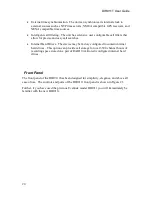
Page 22: ...The 5 by 7 LED array displays the currently active line When in system mode the display flashes S D LCD SCREEN The DIR911t contains a 40 by 4 character LCD display used to present information to the user LCD contrast may be adjusted via the LCD CONTRAST ADJUST thumb wheel Legend J E SOFT KEYS There are 4 soft keys whose function is programmable The bottom row of the LCD display will indicate the c...

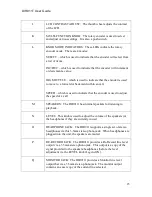
Page 23: ... that the encoder is used to adjust the speed of a call M SPEAKERS The DIR911t has internal speakers for listening to playback N LEVEL This knob is used to adjust the volume of the speakers or the headphones if they are currently in use O HEADPHONE JACK The DIR911t supports a single set of stereo headphones via this 3 5mm stereo phono jack When headphones are plugged into the unit the speakers are...

Page 24: ...ipherals such as USB storage keys to the unit S USB B The DIR911t provides a single USB B peripheral connector This is used for connecting a laptop or similar system to the DIR911t for field service by an authorized Eventide technician Table 1 Front Panel Legend Rear Panel The DIR911t rear panel is shown in Figure 2 ...

Page 25: ...DIR911T User Guide 25 Figure 2 Rear Panel Diagram B A C D E F G H I J K N M L ...

Page 26: ...ide 26 Each of the controls and ports is described in the Table 2 below NOTE A later chapter completely describes the pin numbering and pin function of each port on the front panel Each of the ports is described below ...

Page 27: ...s for the telephone line connection the other is for a telephone Both jacks are parallel and identical G LINE 2 AUX INPUT A balanced 3 5mm phono jack for line 2 auxiliary input NOTE unbalanced connectors can be used the level will be 6dB lower but otherwise function correctly H LINE 2 Telephone Input One plug is for the telephone line connection the other is for a telephone Both jacks are parallel...

Page 28: ...dentical to items G J above M TIME This connector is where an external GPS receiver is connected to the unit A serial port console to the unit is also provided on this connector N ANI This connector is where the ANI serial streams are presented to the unit Table 2 Rear Panel Legend NOTE A later chapter completely describes the pin numbering and pin function signal level for each port on the rear p...

Page 29: ... install the unit 1 Telephone Line Connection For each line to be monitored by the unit connect the line to the appropriate telephone line jack on the unit Each line of the DIR911t has two female RJ 11 jacks that are used to connect the unit to the telephone line Plug the telephone line into one of the two jacks they are the same so it doesn t matter which An extension telephone may be connected t...

Page 30: ...connection Make sure to orient the connector such that it plugs into the unit completely Once plugged in turn the power supply barrel connector clockwise until it locks into place You should not be able to remove the connector barrel from the unit when it is locked into place The unit will power up and display the power up screen shown in Figure 3 Eventide Model DIR911t Multi Line Install Recall R...

Page 31: ...9 At this point you are ready to set the configuration settings to tailor the unit to your environment Powering Down the Unit Units should not be powered off without first halting the system Failure to heed this warning may result in lost configurations and or call database corruption To halt the system enter the setup mode and select the Reboot Halt System configuration screen Press the halt butt...

Page 32: ......

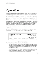
Page 33: ...me the SYSTEM key is pressed unless the unit is already in SYSTEM mode in which case it is ignored Each of these modes is discussed in detail in the sections that follow Main Mode The main mode is entered when the system is powered on or when either the recall or system modes are exited The normal mode screen is shown in Figure 6 16 May 68 04 31 12 Call Ready No Call Len LIVE PREV CALL NEXT CALL R...

Page 34: ...shown following the Playing indicator Paused The unit is playing back a previously recorded call but playback has been paused Rew The unit is rewinding the current call by a factor displayed after the Rew indicator Fwd The unit is fast forwarding the current call by a factor displayed after the Fwd indicator Table 3 Status Field Descriptions Directly below the message counts is the date and time o...

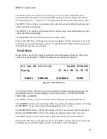
Page 35: ...ntly selected message while providing more control over the playback The Recall mode screen is shown in Figure 7 23 Jun 02 09 54 23 Call 0000001 Ready 01 Jan 88 14 35 15 EMAIL REWIND FORWARD DONE Figure 7 Recall Screen The first three lines of the LCD screen are identical in function and presentation as the main mode screen The main change is in the new soft keys EMAIL REWIND FORWARD and DONE The ...

Page 36: ...tem configuration menus Press the DONE key to exit this menu System Mode System mode is where the unit is configured and monitored The system mode screen is shown in Figure 52 Version 1 7 0B 9 Memory 45 64 224 21MB Lines 2 Remaining recording time 02 16 02 CONFIG INFO ALERTS DONE Figure 9 System Screen The display shows the basic information on the system as well as the amount of time remaining fo...

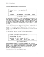
Page 37: ...state If this is the case the user will be placed directly in the system screen NOTE the factory default setting for the DIR911t is in high security mode with a default password of 0000 This means on initial configuration you can simply press the DONE soft key At this point you are now in the system screen This is shown in Figure 11 SELECT CONFIGURATION OPTION Save to USB Drive call s to USB thumb...

Page 38: ... soft key to exit this screen NOTE When a call is saved to an external USB key it is saved with the filename lineN YYYY MM DD HH mm ss WAV where N is the line number YYYY MM DD is the year month day hours minutes seconds of the call NOTE When the call is saved all call metadata date time channel unit Caller ID digits DTMF etc are saved as WAV cue points If MediaWorks MediaAgent is licensed for use...

Page 39: ...save the call A status screen will show the progress If there is a large number of calls that match the call filter this operation may take some time to complete Press the DONE soft key to exit this screen Save to USB Drive by Call Filter The save calls to USB by call filter screen is shown in Figure 15 Save all calls matching the call filter SAVE DONE Figure 15 Save Call to USB Drive By Call Filt...

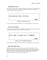
Page 40: ...t to switch to the line with the most recent call that is being recorded The screen is shown in Figure 17 Auto jump to newest call DISABLED DONE Figure 17 Line Auto Jump Setup Screen Use the encoder to enable or disable auto jump Press the DONE key to exit the menu High Traffic Mode Setup The DIR911t operates in one of two traffic modes HEAVY and LIGHT When in HEAVY traffic mode pressing the RECAL...

Page 41: ...l filter to non administrator users When the call filter is disabled pushing the FILTER key will show a screen that indicates that the call filter is disabled and to contact the administrator for information The screen is shown in Figure 19 Call filter use is ENABLED DONE Figure 19 Call Filter Use Setup Screen Use the encoder to enable or disable call filter use Press the DONE key to exit the menu...

Page 42: ...Setup The Automatic Gain Control AGC setup screen is used to enable disable and adjust the various parameters for the both the input and output AGC The screen is shown in Figure 21 Line 1 REC AGC off Max Gain 20dB PLAY AGC off Max Gain 20dB CURSOR DEFAULT DONE Figure 21 AGC Screen The AGC can be enabled or disabled The Gain setting is the upper limit on the AGC gain Use the encoder to adjust the s...

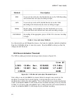
Page 43: ...on process Use the encoder to select the level Press the CURSOR soft key to select between Monitor and Re Record Press the DONE soft key to effect the change and exit the menu Sampling and Compression The sampling and compression setup screen is shown in Figure 23 Sample Rate 8 0kHz Data Compression PCM Linear CURSOR DONE Figure 23 Telephone Activation Level Screen This screen determines the sampl...

Page 44: ...a 2 to 1 compression ratio G726 32Kbps The ITU s G 723 32Kbps flavor of ADPCM This option provides a 4 to 1 compression ratio GSM 6 10 The GSM 6 10 Voice Codec used in the European cellular telephone network This option provides a 9 96 to 1 compression ratio Table 4 Compression Methods Recording Priority The recording priority activity setup screen is shown in Figure 24 Line 1 Recording MIX togeth...

Page 45: ...oder to select the desired priority Press the DONE soft key to effect the change and exit the menu Recording Activation The recording activation mechanism setup screen is shown in Figure 25 Record Activation LINE 1 line aux hook external ENABLE ENABLE DISABLE DISABLE CURSOR DONE Figure 25 Record Activation Screen These settings are used by the DIR911t to decide when it should start recording the s...

Page 46: ...t key to select the source Press the DONE soft key to effect the change and exit the menu VOX Record Activation Threshold The VOX recording activation level setup screen is shown in Figure 26 Line 1 LINE 10dBu Rec DISABLE 29 3dBu AUX 10dBV Rec DISABLE 47 4dBV CURSOR DONE Figure 26 VOX Record Activation Threshold Screen This setting is used by the DIR911t to decide if there is enough voice activity...

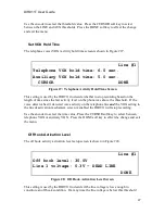
Page 47: ...ne was above the threshold If the voice detector hasn t detected voice activity on the telephone line and the VOX setting in the line deactivation mechanism screen is enabled the DIR911t will stop recording Use the encoder to select the time value Press the CURSOR soft key to select between telephone VOX or auxiliary VOX Press the DONE soft key to effect the change and exit the menu Off Hook Activ...

Page 48: ...own in Figure 29 Line 1 EXT I O pin 7 GND pin 5 line 1 line 2 line 3 line 4 DISABLE DISABLE DISABLE DISABLE DONE Figure 29 Test External Closure Screen This screen is used to show the state of the external connections that may affect the unit s decision to start recording a call Press the DONE soft key to exit the screen Audible Beep Level The audible beep level screen is shown in Figure 30 Line 1...

Page 49: ...R911t uses Caller ID to extract the ANI information and presents it on the screen When set to out of band circuitry external to the DIR911t is responsible for recovering the ANI information and sending it to the unit via the ANI serial ports When set to ANI circuitry external to the DIR911t recovers the Caller ID information and sends it to the unit for display The serial message format is identic...

Page 50: ...he 2nd line and you would set the length to 12 to include all numbers in the phone number including the dashes NOTE The format of ALI data changes from state to state and sometimes from county to county You will need to verify the format of your particular location The DIR911t assumes that the data is always formatted as 16 rows with 32 columns carriage return new line are ignored in the character...

Page 51: ...rchiving task Use the CURSOR key to move between the configuration fields The Centralized Archiving field is used to enable or disable centralized archiving The Server field is used to specify the IPv4 or hostname of the centralized archive destination Turn the encoder to the desired value and press the encoder to select that character and move to the next position The REQ AUTH soft key is used to...

Page 52: ...ived even if they had been previously centralized archived Press the CURSOR to move between the various fields of the date and time Turn the encoder to the desired value Press the DONE soft key to update the pointer and exit this menu NOTE updating the archive pointer may take some time depending on the DIR911t model number and the number of calls currently stored Centralized Archive Status The ce...

Page 53: ...Jul 05 14 27 36 EDT Set 19 Jul 05 14 27 22 America New York Src INT CURSOR SET DONE Figure 36 Date Time Setup Screen This screen is used to set the unit s time and date There are many sources to which the DIR911t can synchronize its internal clock These include its internal battery backed hardware clock Network Time Protocol NTP servers and NMEA GPS serial streams and NENA serial streams ...

Page 54: ... using the NENA 1 format NENA 2 Date Time information is recovered from the Time port on the rear panel using the NENA 2 format NENA NIS Date Time information is recovered from the Time port on the rear panel using the NENA 3 format NENA GORGY Date Time information is recovered from the Time port on the rear panel using the NENA 4 format Table 7 Clock Synchronization Methods Use the CURSOR soft ke...

Page 55: ...ettings Press the SYSTEM key to exit the menu without changing anything for example to view the IPv4 address without reconfiguring the network port Email Address Setup The email address setup screen is shown in Figure 38 Calls Auto off Reports 00Hr Status CURSOR CLEAR TEST DONE Figure 38 Email Address Setup Screen The DIR911t is able to send email when certain system alarms are triggered or to for...

Page 56: ...IR911t will use to send email The Mail Server field is the IP address or fully qualified domain name of the email server The Email From field is the address that is placed in the from field of the email To prevent spam and other email abuse many SMTP servers are configured to authenticate the user before email can be sent So the DIR911t has a Uname user name and Pword password field for entering t...

Page 57: ...lect the desired value Use the CURSOR soft key to select which field to update Press the DONE soft key to effect the change and exit the menu Password Setup The password setup screen is shown in Figure 41 Please set your password 0000 CURSOR INCREASE DECREASE DONE Figure 41 Password Setup Screen This screen is used to set the password for the unit The password is used to control access to the syst...

Page 58: ...shown in Figure 43 Enter the new username and password Username Password CURSOR ADD DONE Figure 43 Add User Screen Use this screen to add new remote users The encoder selects the character Push the encoder to advance the cursor by one position The CURSOR soft key will select either the Username field or the Password field it will also reposition the cursor to the beginning of each field When the U...

Page 59: ... is shown in Figure 45 Line 1 Line Name Line 1 CURSOR DONE Figure 45 Line Naming Screen This screen provides a way to individually name the lines of the DIR911t The line name is predominately used when the DIR911t is configured for centralized archiving or call browsing using Eventide s MediaWorks recorder client Press the LINE button to move through the various lines Turn the encoder to the desir...

Page 60: ...g a configuration creates a file on the USB key named dir911t cfg which contains the entire box configuration Importing a configuration requires a file named dir911t cfg which contains a previously exported DIR911t configuration and requires a system reboot for the imported settings to take effect IMPORT EXPORT the system configuration IMPORT EXPORT DONE Figure 47 RAID Import Export System Configu...

Page 61: ...e Eventide web site www eventide com and retrieve the dir911t sys file itself To begin an update enter the setup mode and select the Firmware Upgrade option You will be presented with the screen shown in Figure 48 STATUS IDLE Press NET to do an Internet Upgrade Press USB to do an USB Upgrade NET USB DONE Figure 48 Update Screen To perform the upgrade via the Internet simply press the NET key The D...

Page 62: ... problem Press the DONE soft key to exit this menu Total Call Count The total call count screen is shown in Figure 46 Recorded Calls 2 Time 00 10 32 Saved Calls 0 Time 00 00 00 Available recording time 69 24 59 DONE Figure 50 Total Call Count Screen This screen provides a way to find the total number of calls stored in the unit Information displayed includes the total number of calls saved and uns...

Page 63: ...ress the REBOOT key to reboot the system Use this if you simply want to restart the unit System Information Screen The information INFO screen is shown in Figure 9 Model 1137 004 S N V 0000005 MID 27FB19200000 PID EF163C900000 MAC 00E0189393CB ADD ONS MW5 CA SP6 MD0 DONE Figure 52 System Information Screen This screen provides various bits of information about the system This information may be us...

Page 64: ...e 53 System Information Screen This screen provides information about anomalies the system has detected Use the KNOB to scroll through the various alerts The DISMISS soft key will delete the currently displayed alert The PREV and NEXT soft keys move to the previous and next alerts Press the DONE soft key to exit this menu ...

Page 65: ...te and time Enabled Yes EDIT DISABLE DONE Figure 54 Call Filter Setup Screen There are four configurable filter types that a call must meet in order to be presented to the user These are date and time incoming line caller ID digits and DTMF digits Setup of these filters is described in the subsections that follow Each filter may be disabled from consideration if it is not needed and that filter wi...

Page 66: ...on certain lines The screen is shown in Figure 56 Include calls that were recorded on Line 1 Line 2 Line 3 Line 4 YES YES YES YES CURSOR DEFAULT MORE LINES DONE Figure 56 Incoming Line Filter Screen Use the CURSOR soft key to select the desired line to change The KNOB is used to change the value of the currently selected field The DEFAULT key will return the screen to the default value which is al...

Page 67: ...its Filter The Caller ID digits filter screen is used to constrain the search to include only calls that were received that start with contain or end with a specified series of Caller ID digits The screen is shown in Figure 58 Include calls whose Caller ID digits begin with CURSOR DEFAULT DONE Figure 58 Caller ID Digits Filter Screen Use the CURSOR soft key to select the desired parameter to chang...

Page 68: ......

Page 69: ... 1 4 and aux 1 4 operation When in split mode channels 1 4 behave as if the Recording Priority Screen were set to Line Input and Channels 5 6 8 would behave as if it were set to Aux Input The activation methods associated with a given input carry over form normal operation From the Record Activation Screen line hook and external are triggers that would be used to activate line input recording i e ...

Page 70: ......

Page 71: ...71 Factory Defaults The Table 8 specifies the factory defaults of the DIR911t ...

Page 72: ...ce Activity Threshold all lines 10dBFS Auxiliary Activity Threshold all lines 10dBFS Off Hook Activity Threshold all lines 30V Phone Input Gain all lines 12dB Auxiliary Input Gain all lines 12dB Autorestore Time 25 Seconds Voice Activity Hold Time 6 Seconds Audible Beep Level OFF ANI Setup all lines Internal Caller ID Re Record Output Level 0dB Monitor Output Level 0dB Ethernet LAN DHCP Table 8 Fa...

Page 73: ...r Guide 73 Connector Pinouts Front Panel This section details the connector pinouts for the connectors located on the front panel of the DIR911t Each connector s relative location on the unit is shown in Figure 59 ...

Page 74: ...DIR911T User Guide 74 Figure 59 Front Panel Connector Locations Headphones Pre Record Monitor USB A USB BS ...

Page 75: ... connector is shown in Figure 60 and the pin description is shown in Table 9 1 4 Figure 60 Front Panel USB A Connector Pin Diagram Pin Description 1 Vbus 2 D 3 D 4 Ground Table 9 Front Panel USB A Connector Pin Description USB B Peripheral Side Connector There is a single Host Side USB B type connector on the front panel This connector is used to connect the unit to standard USB hosts such as lapt...

Page 76: ...r Pin Description Monitor Output Connector There is a 3 5mm Tip Ring Sleeve TRS connector that provides the monitor output signal This connector is used to connect the unit to standard audio recording devices that have industry standard line level inputs The mating connector for this jack is shown in Figure 62 and the pin description is shown in Table 11 ...

Page 77: ...d Output Connector There is a 3 5mm Tip Ring Sleeve TRS connector that provides the re record output signal This connector is used to connect the unit to standard audio recording devices that have industry standard line level inputs The mating connector for this jack is shown in Figure 63 and the pin description is shown in Table 12 Tip Ring Sleve Figure 63 Front Panel Re Record Connector Pin Diag...

Page 78: ...TRS connector that provides the headphone output signal This connector is used to connect the unit to headphones The mating connector for this jack is shown in Figure 64 and the pin description is shown in Table 13 Tip Ring Sleve Figure 64 Front Panel Headphone Connector Pin Diagram Pin Description TIP Left RING Right SLEVE Ground Table 13 Front Panel Headphone Connector Pin Description ...

Page 79: ...IR911T User Guide 79 Rear Panel This section details the connector pinouts for the connectors located on the rear panel of the DIR911t Each connector s relative location on the unit is shown in Figure 66 ...

Page 80: ...DIR911T User Guide 80 USB A Ethernet External Act Time Sync Console Auxiliary Input Telephone Power ALI Input ANI Input ...

Page 81: ...el type connector on the rear panel that provides DC power to the unit This should only be connected to the DC power supply provided with the unit The mating connector for this jack is shown in Figure 67 and the pin description is shown in Table 14 Inner Outer Locking Flange Figure 67 Rear Panel DC Power Connector Pin Diagram Pin Description INNER 12V at 1 5A OUTER Ground Table 14 Rear Panel DC Po...

Page 82: ...hat there are two physical connectors for each line and the two connectors are pinned out identically The connector pin diagram is shown in Figure 68 and the pin description is shown in Table 15 6 1 Figure 68 Rear Panel Telephone Line RJ 11 Connector Pin Diagram Pin Description 1 No Connect 2 No Connect 3 Tip 4 Ring 5 No Connect 6 No Connect Table 15 Rear Panel Telephone Line RJ 11 Connector Pin D...

Page 83: ...gain reduction for single ended signals The mating connector for this jack is shown in Figure 69 and the pin description is shown in Table 16 Tip Ring Sleve Figure 69 Rear Panel Auxiliary Input Connector Pin Diagram Pin Description TIP Audio Signal RING Audio Signal SLEVE Ground Table 16 Rear Panel Auxiliary Connector Pin Description ALI Input Connector A single DB 9 type connector on the rear pan...

Page 84: ... Ground 6 Line 2 ALI Input 7 No Connect 8 Line 4 ALI Input 9 No Connect Table 17 Rear Panel ALI DB 9 Connector Pin Description ANI Input Connector A DB 9 type connector on the rear panel is used to connect ANI providing equipment to the unit The serial signals are standard RS 232 levels The pin diagram for this connector is shown in Figure 71 and the pin description is shown in Table 18 ...

Page 85: ...No Connect Table 18 Rear Panel ANI DB 9 Connector Pin Description External Activity Connector A single DB 9 type connector on the rear panel is used to control the external activity capabilities of the box This connector provides a standard RS 232 signal level input for each line that can be used to activate the line The connector also provides a standard RS 232 signal level output for each line t...

Page 86: ... Rear Panel External Activity DB 9 Connector Pin Diagram Pin Description 1 Line 1 Active Input 2 Line 3 Active Input 3 Line 2 Activate Output 4 Line 3 Activate Output 5 Ground 6 Line 2 Active Input 7 Line 1 Activate Output 8 Line 4 Active Input 9 Line 4 Activate Output Table 19 Rear Panel External Activity DB 9 Connector Pin Description ...

Page 87: ...s The pin diagram for this connector is shown in Figure 73 and the pin description is shown in Table 20 1 6 5 9 Figure 73 Rear Panel Time Sync Console DB 9 Connector Pin Diagram Pin Description 1 Time Sync Pulse Per Second Input 2 Time Sync Receive Input 3 Time Sync Transmit Output 4 5V 250mA Fused Power 5 Ground 6 No Connect 7 Console Transmit Output 8 Console Receive Input 9 System Alarm Output ...

Page 88: ...s connector is shown in Figure 74 and the pin description is shown in Table 21 1 4 Figure 74 Rear Panel USB A Connector Pin Diagram Pin Description 1 Vbus 2 D 3 D 4 Ground Table 21 Rear Panel USB A Connector Pin Description Ethernet Connector A single RJ 45 type connector on the rear panel is used to connect the unit to an Ethernet LAN The pin diagram for this connector is shown in Figure 75 and t...

Page 89: ...Figure 75 Rear Panel Ethernet RJ 45 Connector Pin Diagram Pin Description 1 Transmit 2 Transmit 3 Receive 4 No Connect 5 No Connect 6 Receive 7 No Connect 8 No Connect Table 22 Rear Panel Ethernet RJ 45 Connector Pin Description ...

Page 90: ......

Page 91: ...Engineers www ieee org EIA232 Specification otherwise known as RS 232 Available from Electronic Industries Associations www eia org Understanding Telephone Electronics Third Edition by Stephen J Bigelow ISBN 0 672 27350 0 Sound Reinforcement Handbook by Gary Davis and Ralph Jones ISBN 0 88188 900 8 Protocols Network Time Protocol More information is available at www ntp org SSH The Secure Shell by...

Page 92: ......
Page 93: ...er Setup Screen 65 Call Filter Use Setup 41 Call Filter Use Setup Screen 41 Caller ID Digit Filter 67 Caller ID Digits Filter Screen 67 Canada 4 Centralized Archive Pointer 52 Centralized Archive Pointer Setup Screen 52 Centralized Archive Setup Screen 51 Centralized Archive Status 52 Centralized Archive Status Screen 52 Centralized Archiving 51 Chapters Connector Pinouts 73 Factory Defaults 71 In...

Page 94: ...al Side 75 Console Connector 87 Contacting Eventide 3 D Date 53 Date Time Setup Screen 53 Date and Time Filter 65 Date and Time Filter Screen 66 Delete User 59 Delete User Screen 59 DTMF Digits Filter 66 DTMF Digits Filter Screen 67 E e mail 55 Email Address Configuration 55 Email Address Setup Screen 55 Email Server Configuration 56 Email Server Setup Screen 56 Ethernet 54 91 Ethernet Connector 8...

Page 95: ...vation Level 47 Off Hook ActivationScreen 47 Operation 33 Modes 33 P Panel Front 20 Rear 24 Password Screen 37 Password Setup 57 Password Setup Screen 57 Power Connector 81 Power Up Screen 30 Precautions 3 Protocols NTP 91 SSH 91 R RAID Export Configuration Screen 60 RAID Import Configuration Screen 60 RAID Status 61 RAID Status Screen 62 Rear Panel 24 Connectors 79 Recall 35 36 Recall Mode 35 Rec...

Page 96: ...reen 47 Password 37 Password Setup 57 RAID Status 62 Recall 35 RecallEmail 36 Recording Priority 44 Re Record Output Level Adjust 43 Sampling 43 Saving to USB drive 38 Saving to USB drive by date range 39 Saving to USB drive by filter 39 Saving to USB drive by number 38 Security Level 57 Split Mode 60 System Alerts 64 System Configuration 37 System Halt Reboot 63 System Information 63 System Mode ...

Page 97: ...T User Guide 97 Total Call Count Screen 62 U Update Screen 61 Upgrade 61 USB 91 USB A Host Side Connectors 88 USB B Peripheral Connector 75 USB Drive 38 V VOX Activation Level 46 VOX Hold Time 47 W Warranty 6 ...

Reviews: