


TS
108
TS
107
First Steps
8
OPERATION
3.
OPERATION
3.1.
First Steps
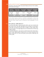
Rear Connections & DIP Switches
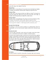
Check the package components (loudspeaker, remote c batteries,
user’s manual, power cord).
Check the setting of the DIP Switches (Off).
Connections: there are XLR input and output connectors on the rear side
that allow the connection of balanced and unbalanced devices (signal
sources, active monitors, etc.).
•
Balanced XLR pin assignment: 1 = Shield, 2 = hot (+), 3 = cold(-).
•
Unbalanced XLR pin assignment: 1+3 = Shield, 2 = Signal.
The rear side also offers an unbalanced RCA input connector for the
connection to the dedicated Sub out of an EVE Audio SC203 Master/Slave
system.
•
RCA pin assignment: Sleeve = Shield, Tip = Signal.
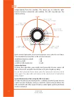
Depending on the setting of the Max. Input DIP switch on the rear panel,
the maximum level of the source signal should not 8 dBu or
+22 dBu (see Max. Input). If the input is overloaded the LED ring will start
blinking.