background image

EVCO S.p.A. 

Vcolor 869/879

 | Installer manual ver. 2.2 | Code 144VC869E214 


page 82 of 94 


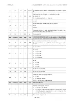
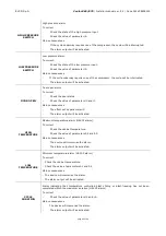
HIGH PRESSURE 

SWITCH 

High pressure alarm. 

To correct 

Check the state of the high pressure input. 

Check the value of parameter i6. 

Main consequences 

If the cycle underway requires use of the compressor, the cycle will be interrupted. 

The alarm output will be activated. 

LOW PRESSURE 

SWITCH 

Low pressure alarm. 

To correct: 

Check the state of the low pressure input. 

Check the value of parameter i9. 

Main consequences 

-        If the cycle underway requires use of the compressor, the cycle will be interrupted. 

The alarm output will be activated. 

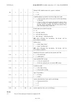
DOOR OPEN  

Door open alarm. 

To correct 

Check the door status. 

Check the value of parameters i0 and i1. 

Main consequences 

The effect set by parameter i0. 

The alarm output will be activated. 

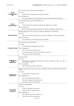
HIGH 

TEMPERATURE 

Maximum temperature alarm (HACCP alarm). 

To correct 

Check the cabinet temperature. 

Check the value of parameters A4 and A5. 

Main consequences 

The device will memorise the alarm. 

The alarm output will be activated. 

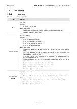
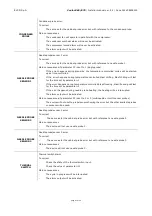
LOW 

TEMPERATURE 

Minimum temperature alarm (HACCP alarm). 

To correct 

-  Check the cabinet temperature. 

-  Check the value of parameters A1 and A2. 

Main consequences 

-  The device will memorise the alarm. 

-  The alarm output will be activated.  

CYCLE 

DURATION  

Alarm  indicating  that  temperature  controlled  blast  chilling  or  blast-freezing  has  not  been 
completed within the maximum duration (HACCP alarm). 

To correct 

Check the value of parameters r5 and r6. 

Main consequences 

-        The device will memorise the alarm. 

The alarm output will be activated. 

Summary of Contents for Vcolor 318 M

Page 1: ...S p A Vcolor 869 879 Installer manual ver 2 2 Code 144VC869E214 page 1 of 94 Vcolor 869 879 Controllers for blast chillers with customizable graphical skin ENGLISH INSTALLER MANUAL ver 2 2 CODE 144VC869E224 ...

Page 2: ...bed precautions Keep this document with the device for future consultation Only use the device in the ways described in this document Do not use the device as safety device The following symbols are used in this document indicates a suggestion indicates a warning Disposal The device must be disposed of according to local regulations governing the collection of electrical and electronic waste ...

Page 3: ...ER INTERFACE 21 5 1 Initial information 21 5 2 Initial switch on 21 5 3 Switching the device on and off 23 5 4 Lock unlock keypad 23 5 5 Silencing the buzzer 23 5 6 Door open signal 23 6 OPERATION 24 6 1 Initial information on operating cycles 24 6 2 Initial information on the needle probe 24 6 3 Selecting the operating mode 25 7 BLAST CHILLING 26 7 1 Blast chilling blast freezing and conservation...

Page 4: ...9 11 4 Pump down solenoid valve management 60 11 5 Evaporator fan management 60 11 6 Condenser fan management 62 11 7 Alarm output management 62 11 8 Needle probe heating management 62 11 9 Cabinet sterilisation management 62 11 10 Defrost output management 62 11 11 Thawing heater management 63 11 12 Proofing and slow cooking heater management 63 11 13 Humidifier management 63 11 14 Humidifying st...

Page 5: ... 17 2 ECTSFD004 230 VAC 12 VAC 20 VA safety transformer 86 17 3 EVIF20SUXI Non optoisolated RS 485 USB serial interface 86 17 4 0812000002 USB plug for panel installation 87 17 5 0810500018 0810500020 Connecting cables 87 17 6 EVDFAN1 Phase cutting speed regulator for single phase fans 87 17 7 EVUSB4096M 4GB USB flash drive 88 17 8 EVIF25SWX EVlink Wi Fi RS485 module 88 18 TECHNICAL SPECIFICATIONS...

Page 6: ...ing retarding proofing and slow cooking cycles The controller has intuitive navigation with graphical monitoring of cycles in progress and its innovative programmable platform enables to independently personalise the graphical skin to an advanced degree to set up the recipe book with high quality photographs and to add new machine interface languages On demand the controllers can be equipped with ...

Page 7: ... EVDFAN1 EVIF25SWX Power supply control module 115 230 VAC 115 230 VAC user interface powered by control module 12 VAC additional modules 115 230 VAC 230 VAC powered by control module Analogue inputs cabinet probe PTC NTC PTC NTC needle probe sensor 1 PTC NTC PTC NTC needle probe sensor 2 PTC NTC PTC NTC needle probe sensor 3 PTC NTC PTC NTC evaporator probe PTC NTC PTC NTC condenser probe PTC NTC...

Page 8: ...X Digital outputs electro mechanical relays A res 250 VAC configurable compressor 30 A 30 A defrost 8 A 8 A evaporator fan 8 A 8 A condenser fan 8 A 8 A door heater 8 A 8 A thawing heater 16 A 16 A alarm configurable 1 16 A 16 A pump down valve configurable 2 8 A 8 A needle probe heater configurable 3 8 A 8 A cabinet heater 30 A steam generator 16 A steam injection 8 A auxiliary output 16 A Other ...

Page 9: ...edle probes management of special cycles fish sanitation thawing and ice cream hardening management of retarding proofing and slow cooking special cycles recording HACCP data and graphics processing in real time ready to use OEM recipes and storage of user recipes Wi Fi connectivity for remote management through EPoCA portal 1 if a PWM speed regulator is present and enabled parameter E16 1 the eva...

Page 10: ...869 879 Installer manual ver 2 2 Code 144VC869E214 page 10 of 94 2 DESCRIPTION 2 1 User interface description The diagram below shows the front view of the user interface in the vertical format PART DESCRIPTION 1 display ...

Page 11: ...DESCRIPTION 1 USB port 2 RS 485 MODBUS port 3 dip switch for the termination resistor for the RS 485 MODBUS port 4 power supply for the user interface and connection between the user interface and the control module 5 dip switch for the resistor connecting the user interface and the control module 6 appliance earthing For more information see subsequent sections ...

Page 12: ...relay 4 compressor relay 5 door heater relay 6 door switch low pressure switch and high pressure switch compressor thermal switch 7 thawing heater relay 8 alarm relay 9 pump down relay and needle probe heater 10 cabinet evaporator and condenser probe 11 multi point probe or needle probes up to 3 sensors 12 unused 13 unused 14 output for phase cutting speed regulator for EVDFAN1 single phase fans 1...

Page 13: ...TION 3 1 Vcolor 869M user interface measurements The picture below shows the measurements of the 5 inch user interface measurements are expressed in mm inches 3 2 Vcolor 869L user interface measurements The picture below shows the measurements of the 7 inch user interface measurements are expressed in mm inches ...

Page 14: ...module measurements The picture below shows the measurements of the Vcolor 819 control module measurements are expressed in mm inches 3 4 Multi functional module measurements The picture below shows the measurements of the Vcolor 819 multi functional module measurements are expressed in mm inches ...

Page 15: ...94 3 5 User interface installation Mounting of 7 interfaces Vcolor 869 L Flush fit installation from behind the panel using threaded studs Mounting of 5 interfaces Vcolor 869 M Flush fit installation from behind the panel using threaded studs From the front of the panel with hooks ...

Page 16: ... sources heaters hot air ducts etc equipment with a strong magnetic field large diffusers etc in places subject to direct sunlight rain damp excessive dust mechanical vibrations or shocks Any metal items close to the control module must be at a sufficient distance so as not to compromise the safety distance any cabling must be placed at least 2 cm away In compliance with safety regulations the dev...

Page 17: ... 869 879 Installer manual ver 2 2 Code 144VC869E214 page 17 of 94 4 ELECTRICAL CONNECTION 4 1 Electrical connection of Vcolor 869M The picture below shows the electrical connection of the controller with 5 inch display ...

Page 18: ...EVCO S p A Vcolor 869 879 Installer manual ver 2 2 Code 144VC869E214 page 18 of 94 Details of EVlink Wi Fi electrical connection ...

Page 19: ...S p A Vcolor 869 879 Installer manual ver 2 2 Code 144VC869E214 page 19 of 94 4 2 Electrical connection of Vcolor 869L The picture below shows the electrical connection of the controller with 7 inch display ...

Page 20: ...om a cold to a warm place the humidity may cause condensation to form inside Wait about an hour before switching on the power Make sure that the supply voltage electrical frequency and power of the device correspond to the local power supply See section 17 TECHNICAL SPECIFICATIONS Disconnect the device from the power supply before doing any type of maintenance Do not use the device as safety devic...

Page 21: ...ails during stand by or on mode when power is restored the device will return to the mode set before the failure If the power supply fails during run mode when power is restored the device will operate as follows if blast chilling or blast freezing was in progress the cycle will resume taking into account the duration of the power loss if a conservation cycle was running this will continue using t...

Page 22: ...screen Based on how the machine is configured through parameter E13 the Home screen will display either the menu of the BLAST CHILLER mode or the menu of the MULTIFUNCTION mode Blast chiller mode home screen Multifunction mode home screen Page 1 Page 2 If the power supply has been cut off long enough to cause a clock error RTC code it will be necessary to reset the date and time The date and time ...

Page 23: ... be locked by setting parameter E7 to 1 locking the keypad after the period of inactivity set by parameter E8 If the keypad is locked a pop up will appear when it is touched indicating that it is locked and how to unlock it It can be unlocked by dragging a finger to the right 5 5 Silencing the buzzer Press any key while the buzzer is sounding 5 6 Door open signal When the door is opened the signal...

Page 24: ...ng the needle probe drying Upon use of the optional expansion module the following functions are also available proofing slow cooking For more information see the subsequent sections 6 2 Initial information on the needle probe This device is capable of managing multipoint needle probes with up to three sensors or multineedle probes up to three probes To set the type of probe to be used configure p...

Page 25: ...edle probe or multi timer cycle see chapter 7 Enables special cycles in which it is possible to select one of the special cycles available according to the configuration of the machine see chapter 8 In the Bast Chilling mode these functions can be accessed through the area Makes it possible to select a retarding proofing cycle detailing date and time for cycle end see section 8 8 Makes it possible...

Page 26: ...ode selected See sections 7 1 and 7 2 Enables selection of a standard blast freezing cycle uploading the relevant pre settings On the same screen it is possible to select soft mode when blast freezing consists of two phases with different set points When blast freezing is complete the corresponding conservation phase is run with the set points established for the blast freezing mode selected See s...

Page 27: ...which will deactivate the needle probe area and the time controlled area will be activated The cycle selected will use the preloaded settings for that cycle but pressing area makes it possible to change the main settings within the permitted range which are shown on the display To change all the various set points for the phases of the selected cycle expert mode can be enabled by pressing area Onc...

Page 28: ...est see section 7 6 1 While the cycle is in progress the display will show the main set points The graphic charting the temperature will be displayed pressing the key The key will be displayed after 5 minutes from the cycle start and updates will take place with a one minute frequency The cycle can be stopped at any time by pressing the key On completion of the blast chilling blast freezing cycle ...

Page 29: ...s an example for setting a hard blast chilling slow cooking holding 7 2 Hard blast chilling soft blast freezing and conservation It is possible to select a hard blast chilling soft blast freezing cycle on the blast chilling blast freezing settings screen by pressing area or Before selecting this mode make sure the type of cycle temperature or time controlled has been set This cycle consists of two...

Page 30: ...the multineedle probe cycle Continuous cycle needle probe Continuous cycle time control Press the key to start up the cycle and this will only finish when all the needle probes have reached the set temperature or all the timers have elapsed after which the controller moves on automatically to the conservation phase 7 3 1 Multineedle probe mode The continuous cycle using multineedle probes can be r...

Page 31: ...ues can be enabled by pressing the pencil icon and setting a time once the cycle is underway When the time period is set and the timer setting confirmed the timer count starts up immediately Each timer operates independently and on completion of the period it can be reset starting the timer count up again The cycle only terminates when all the set timers have elapsed When the timer count is comple...

Page 32: ...ase which by default is a needle probe phase It is possible to change the probe phase to a time controlled phase and to set the relative set points To add any more phases press area while to eliminate any phase previously set in the program press area It is possible to move between the various phases using the arrows at the top of the screen Once the desired phases have been selected and set up pr...

Page 33: ...l become orange Set the desired value using the key Once set up is complete press the next to the edited value and return to the previous screen 7 5 2 Setting the product temperature set point Proceed as described for the cabinet set point after pressing area for the product temperature or the temperature indicated by the needle probe 7 5 3 Setting the cycle duration Proceed as described for the c...

Page 34: ...cycles are preceded by a two phase test to check that the needle probe is correctly inserted If the needle probe is not enabled or if parameter P3 is set at 0 only time controlled cycles can be selected The test consists of two phases the second only carried out if the first was not successfully completed Phase one is successfully completed if the gap between the temperature detected by the needle...

Page 35: ...ting cycles carried out and any alarms The type of data to be recorded can be set using the menu accessible from the service area see section 12 1 These data are available for subsequent download to a USB device see section 13 4 7 6 3 Cycle end If the temperature controlled blast chilling blast freezing cycle is successfully completed in which the centre of the product reaches the required tempera...

Page 36: ...69 879 Installer manual ver 2 2 Code 144VC869E214 page 36 of 94 In time controlled cycles pressing the key will bring up the screen granting access to the following functions record the cycle just performed in the memory ...

Page 37: ...nables selection of a fish sanitation cycle a function always shown see section 8 1 Pressing this area enables selection of a thawing cycle a function always shown see section 8 2 Pressing this area enables selection of a manual defrost cycle a function always shown see section 8 3 Pressing this area enables selection of an ice cream hardening cycle a function always shown see section 8 4 Pressing...

Page 38: ...area enables selection of a fish sanitation cycle This special cycle consists of the following phases blast chilling with the cabinet set point set by parameter r19 and with the product temperature set point set by parameter r20 holding for the time period set by parameter r21 and the cabinet set point given by r20 conservation with the cabinet set point given by r22 The arrows at the top make it ...

Page 39: ...et by r20 is also the working set point during holding When the holding period has elapsed the device will move on automatically to conservation The probe insertion test is always carried out at the beginning of the cycle if the test is not completed the buzzer sounds and the cycle is interrupted During blast chilling the device shows the temperature recorded by the needle probe the cabinet temper...

Page 40: ...ets of parameters according to the following framework Load band Initial cabinet set point Final cabinet set point Cycle duration Lightly loaded r25 r28 r32 Partly loaded r26 r29 r33 Full loaded r27 r30 r34 These three parameters will be used to control the working cabinet set points and the duration of the thawing cycle equally divided into five phases following on from each other as shown Phase ...

Page 41: ...he thawing cycle the buzzer sounds after which the machine moves on to a conservation phase its set point set by parameter r31 for an indefinite period The fans will work at the speed set by parameter F34 It is not possible to run defrosting cycles during thawing while during the conservation phase an automatic defrost can be run at intervals set by parameter If the door is opened the heater will ...

Page 42: ...ezing cycle d5 Defrost start up delay from the start of conservation after blast chilling blast freezing d7 Drip duration d15 Minimum compressor switch on duration for starting hot gas defrost d16 Pre drip duration can be set if hot gas defrost is selected The type of defrost can be selected by parameter d1 There are four ways of performing a defrost cycle d1 0 Electric defrost d1 1 Hot gas defros...

Page 43: ...by parameter d3 8 4 Ice cream hardening Pressing this area enables selection of an ice cream hardening cycle This is a time controlled blast freezing cycle with the set point provided by parameter r8 and the duration by parameter r24 At the end of the time set by r24 there is no move to a conservation phase the hardening cycle continues until the key is pressed If the door is opened the time count...

Page 44: ...cle Sterilisation ends when the time set by parameter u6 has elapsed after the key has been pressed or if the door is opened During sterilisation the cabinet sterilisation relay is active If parameter u11 is set to 1 the evaporator fans are also active If the fans are run at variable speeds there will be 100 ventilation during sterilisation The display will show the count down for the remaining ti...

Page 45: ...he cell temperature is greater than 0 C in the following operations blast chilling see example blast freezing defrosting slow cooking cold storing If the ionizer is active but the cell temperature drops below 0 C the ionizer is switched off button icon disabled and remains in this condition even if the cell temperature rises above 0 C in this second case however the user can reactivate the ionizer...

Page 46: ...Pressing this area enables selection of a needle probe or probes heating cycle The cycle can be run only if the door is open This cycle can also be run automatically if the key is pressed during conservation following a blast chilling defrosting cycle The needle probe heating output is activated at maximum for the time set by parameter u8 or until the temperature indicated by the needle probe has ...

Page 47: ...ect the cycle The cycle stops when the prescribed time has elapsed or when the key is pressed 8 9 Retarding proofing Pressing this area enables selection of a retarding proofing cycle This function can only be enabled if an expansion has been set parameter E12 8 9 1 Description of retarding proofing The controller provides complete control for retarding proofing cabinets for bread or pastry by man...

Page 48: ...active and has a NEUTRAL ZONE adjustment the working setpoint is set by the end user The duration in hours and minutes and the evaporator fan speed are set by the end user 8 9 1 4 PROOFING phase Temperature regulation is active and has a NEUTRAL ZONE adjustment the working setpoint is set by the end user Moving from the re awakening setpoint previous phase to the proofing setpoint can be gradual w...

Page 49: ...will automatically increase the conservation time phase 2 to fill the time gap The cycle can be interrupted manually during any phase by holding the key down for 4 seconds N B Phase 5 baking delay is optional and does not require a duration to be set and therefore if enabled it can only be terminated manually by pressing the key 8 9 2 2 Making changes to cycle phases Before starting up a cycle the...

Page 50: ...5 Proofing Cabinet setting rH4 30 C Humidity setting rU7 80 rH Duration setting rH9 180 min Ventilation F44 5 Conservation Cabinet setting rH5 25 C Humidity setting rU8 80 rH Enable phase Inf enabled disabled Ventilation setting F45 5 8 9 2 3 Making changes to cycle end date and time The icon is displayed on the bottom left of the screen showing the date and time set for the end of the cycle which...

Page 51: ...be enabled if an expansion has been set see parameter E12 After selection of the slow cooking function a screen will appear on which it is possible to view and modify the relevant set points and to decide whether to set up a temperature or time controlled process It is not possible to modify the set points while the cycle is in progress The slow cooking pre settings use the following parameters rH...

Page 52: ...s are used to set up a holding or conservation phase rH13 cabinet set point for holding phase rU10 humidity in holding F41 fan speed If a holding phase has been enabled following a slow cooking cycle this will be activated at the set temperature and humidity and it will have an indefinite duration If blast chilling or blast freezing has been enabled this will be performed according to the procedur...

Page 53: ...ng heating or neutral zone mode The presettings of the cooling cycle are those of the blast chilling while the presettings of heating and neutral zone cycles are those of slow cooking Before starting the cycle all the values of a conservation cycle can be modified The cycle starts when the area is pressed and remains active until the area is pressed ...

Page 54: ...o any language desired If a category does not include any recipes that category will not be displayed Parameter E15 defines whether OEM recipes can be overwritten by the user An easy procedure makes it possible to save but not to export OEM recipes via USB In this event it is necessary to proceed with an update following the procedure below From the stand by screen select the CONFIGURATION icon Se...

Page 55: ...ture controlled cycles In the latter case the time required to reach the core temperature is saved Recipes can be saved in the following ways During conservation after a customized blast chilling blast freezing cycle When the key is pressed the device will offer to save the recipe used save a recipe before starting the cycle Select a recipe already present modify it and save it Below is an example...

Page 56: ...board is now accessible press to exit the procedure without saving Type the desired recipe name and press to confirm If you wish to change the recipe name proceed as follows Touch the name of the desired recipe Touch to confirm you want to overwrite the alphabetic keyboard is now accessible press to exit the procedure without saving Cancel the displayed recipe name and type the new name you wish t...

Page 57: ... Enter the menu and select the desired recipe If you wish to modify the recipe touch the field to to edit cabinet temperature needle temperature time fan speed to access the recipe settings In the Cycle Summary page touch the key to start the recipe 9 2 3Deleting MY COOKBOOK recipes To delete a recipe operate as follows 1 From MY COOKBOOK list select the recipe you wish to delete and press the ico...

Page 58: ...ion opens the following screen Set the required set point value and press area to start the cabinet pre cooling cycle The screen below will be displayed showing the pre cooling cycle in process The fan speed is fixed and set by parameter F28 Press the key to stop pre cooling Once the required cabinet set point has been reached the buzzer sounds and the cycle continues maintaining the cabinet tempe...

Page 59: ...p down solenoid valve is first deactivated and once the delay set by parameter u12 has elapsed the compressor will also switch off If there is a fault with the cabinet probe during a conservation cycle the compressor is activated on a cyclical basis according to the values of parameters C4 and C5 if this is a conservation phase following blast chilling or according to the values of parameters C4 a...

Page 60: ...mbined with the EVDFAN1 cutting phase module or in an On Off mode if one of the relays is configured as evaporator fan The two outputs PWM or relay work independently one of another If the evaporator fan is managed through a PWM analogue output the fan speed can be set for each phase When the fan is switched on the controller will manage a speed F21 and a start up time F22 After F22 time elapses t...

Page 61: ...ameter F1 value They are only switched on again if the cabinet temperature falls below the F17 F8 value and that of the evaporator probe falls below F1 F8 Sanitation conservation The fans are always managed in parallel with the compressor Thawing The fans are always active Defrosting During defrosting the evaporator fans are switched off if the parameter d1 value is set to 0 or 1 They are switched...

Page 62: ... Defrosting The fans are managed according to the value set by parameter F48 on or off 11 7 Alarm output management This function is only available if one of the relays is configured as alarm This activates when an alarm is set off and deactivates when the alarm stops 11 8 Needle probe heating management This function is only available if one of the relays is configured as needle probe heating Thi...

Page 63: ...o the set point value 11 13 Humidifier management This function is only available if one of the relays is configured as steam injection This function is activated on the basis of the humidity percentage set For example if this is set at 60 the output is activated for 60 of the time set by parameter rU3 and deactivated for the time set by rU2 rU3 The ON and OFF humidifying cycle repeats itself unti...

Page 64: ...tions configure parameters using password 19 restore default values as in the parameter table in Chapter 14 using password 149 restore OEM recipes sing password 99 12 3 Internal values The INTERNAL VALUES area displays the list of available functions as follows alarms input and output status compressor operating hours set date time select HACCP data reset internal values From the reset internal va...

Page 65: ...e is in stand by and no procedure is underway 2 Insert the USB flash drive into the USB port and wait until the menu is displayed 3 Touch UPLOAD PROGRAMS 4 When the upload is complete remove the USB flash drive from the device USB port 13 1 2 Downloading program settings controller USB To download the settings of the programs operate as follows 1 Make sure the device is in stand by and no procedur...

Page 66: ... is in stand by and no procedure is underway 2 Insert the USB flash drive into the USB port and wait until the menu is displayed 3 Touch DOWNLOAD HACCP DATA 4 Select date and hour of start for historical data recording 5 Touch to confirm A file named haccp csv will be generated 6 When the download is complete remove the USB flash drive from the device USB port If the language in use is not a Weste...

Page 67: ...use solution for easily accessible monitoring operations even for entry level users while offering all the typical functions of professional platforms With appropriate protection measures for access and data the system makes it possible for one or more enabled users to operate remotely on the unit to configure its parameters view HACCP data also in graphic form and to download records in the most ...

Page 68: ...ondenser probe calibration if P5 1 CA4 0 25 25 C F 1 Needle probe 1 calibration CA5 0 25 25 C F 1 Needle probe 2 calibration if P9 1 CA6 0 25 25 C F 1 Needle probe 3 calibration if P9 1 P0 0 0 1 Type of probe 0 PTC 1 NTC P2 0 0 1 Temperature measurement unit 0 C 1 F P3 1 0 3 Type of needle probe 0 not enabled 1 single probe 2 multineedle probe 3 multi sensor probe See also P9 P4 1 0 1 Enable evapo...

Page 69: ...se of hard blast chilling See also parameter r0 r10 2 50 99 C F 1 Cabinet temperature set point during conservation after blast chilling hard blast chilling and continuous cycle See also parameter r0 r11 20 50 99 C F 1 Cabinet temperature set point during conservation after blast freezing and soft blast freezing See also parameter r0 r12 5 50 99 C F 1 Cabinet temperature set point during pre cooli...

Page 70: ...ure set point for post thawing conservation r32 240 1 999 min Light load thawing duration r33 480 1 999 min Medium load thawing duration r34 720 1 999 min Heavy load thawing duration r35 15 50 99 C F 1 Cabinet temperature set point for customized blast chilling r36 10 50 99 C F 1 Product temperature set point for customized blast chilling r37 240 1 999 min Duration of time controlled customized bl...

Page 71: ...ofing rH16 1 0 10 C F 1 Neutral zone relative threshold for thawing rH17 2 1 15 C F 1 Cabinet set point differential for activating heater during thawing rH18 2 1 15 C F 1 Cabinet set point differential for activating compressor during thawing rH19 45 1 600 s Heater cycle time for thawing rH20 4 1 10 s Heater on time for thawing rH21 1 0 10 C F 1 Neutral zone threshold for the conservation phase P...

Page 72: ...e C7 90 0 199 C F 1 Condenser temperature above which the compressor locked alarm is activated COMP LOCKED code once the time set for C8 has elapsed C8 1 0 15 min Activation delay of the compressor locked alarm COMP LOCKED code due to threshold C7 exceeded C9 30 0 240 min Compressor on time during cabinet probe error CABINET PROBE code happening during conservation after blast freezing See also pa...

Page 73: ... 0 0 99 min Pre drip time if d1 is set to 1 hot gas defrost in which the compressor and the evaporator fan are off and the defrost output remains activate PAR DEFAULT MIN MAX U M TEMPERATURE ALARMS A1 10 0 99 C F 1 Cabinet temperature below which the minimum temperature alarm is activated in relation to the working set point i e r10 A1 during conservation after blast chilling and r11 A1 during con...

Page 74: ... C F 1 Parameter F1 and F17 differential F15 15 0 240 s Evaporator fan delay from when the door is closed or the door switch input is deactivated F17 90 50 199 C F 1 Cabinet temperature above which the evaporator fan is switched off during pre cooling blast chilling blast freezing sanitation ice cream hardening blast chilling for proofing cycle See also parameter F8 F19 20 0 100 Evaporator fan min...

Page 75: ...re above which the condenser fan switches on F47 30 0 240 s Condenser fan switch off delay from when the compressor is switched off only if the condenser probe is not present F48 0 1 0 Condenser fan status during defrosting 0 off 1 on F49 0 0 1 Fan operating mode during conservation 0 parallel to the compressor 1 always ON F50 0 0 1 Fan operating mode during slow cooking 0 always ON 1 ON if heatin...

Page 76: ...meter F15 i1 0 0 1 Door switch input polarity 0 normally open input active with contact closed 1 normally closed input active with contact open i2 5 1 120 min Door open time for door open alarm record 1 alarm not signalled i5 unused i6 0 0 1 High pressure input polarity 0 normally open input active with contact closed 1 normally closed input active with contact open i7 5 1 240 s High pressure alar...

Page 77: ...ied under parameter u01c u06c 7 0 12 Function managed by output K6 Same settings as specified under parameter u01c u07c 8 0 12 Function managed by output K7 Same settings as specified under parameter u01c u08c 9 0 12 Function managed by output K8 Same settings as specified under parameter u01c u09c 10 0 12 Function managed by output K9 Same settings as specified under parameter u01c u10c 13 0 15 F...

Page 78: ...n protocollo di comunicazione MODBUS EVLINK WIFI L1 5 1 240 min Data recording interval during the main cycles The interval is the same both for the internal data logger and for EVLINK LA 247 1 247 device address Lb 3 0 3 baud rate 0 2 400 Bd 1 4 800 Bd 2 9 600 Bd 3 19 200 Bb LP 2 0 2 parity 0 none 1 odd 2 even PA1 426 99 999 EPoCA level 1 password PA2 824 99 999 EPoCA level 2 password bLE 1 0 99 ...

Page 79: ...g 3 slow cooking retarding proofing NB when changing this parameter the device will be automatically restarted E13 0 0 1 Machine type 0 Home blast chiller 1 Home multifunction NB when changing this parameter the device will be automatically restarted E14 0 1 0 Operating mode when needle probe insertion test fails 0 time controlled 1 needle probe E15 0 1 0 Save modified OEM recipes 0 in the user re...

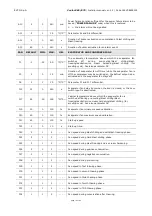
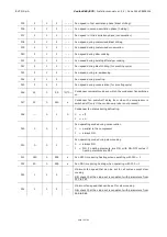
Page 80: ... If the error happens during blast chilling or blast freezing the cycle will continue with the compressor in continuous mode If the error happens during conservation the compressor will operate according to parameters C4 and C5 or C9 If the error happens during a proofing slow cooking or a thawing cycle the cycle will be interrupted The minimum temperature alarm will never be activated The maximum...

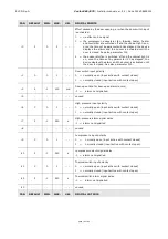
Page 81: ...meter r1 If the error happens during temperature controlled blast freezing blast freezing will last for the time set by parameter r2 If the error happens during needle probe heating the heating will be interrupted The alarm output will be activated Main consequences if parameter P3 is set to 2 or 3 multineedle or multi sensor probes The device will not use the probe sensor showing the error but th...

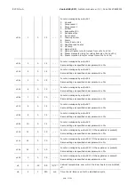
Page 82: ... Check the value of parameters i0 and i1 Main consequences The effect set by parameter i0 The alarm output will be activated HIGH TEMPERATURE Maximum temperature alarm HACCP alarm To correct Check the cabinet temperature Check the value of parameters A4 and A5 Main consequences The device will memorise the alarm The alarm output will be activated LOW TEMPERATURE Minimum temperature alarm HACCP ala...

Page 83: ...ntrolled cycle will be interrupted POWER FAILURE Power failure alarm HACCP alarm To correct Check the device power supply connection Main consequences The device will memorise the alarm Any cycle underway will resume when power is restored The alarm output will be activated SANITATION PROBE INSERTION Sanitation alarm To correct Check that the needle probe has been correctly inserted and check the ...

Page 84: ...ted alarm To correct Check that the needle probes have been correctly inserted and check the value of parameters r17 and r18 Main consequences The temperature controlled cycle in progress will be converted to a time controlled cycle EXPANSION COMMUNICATIO NS User interface expansion module communication error To correct Check the user interface expansion module connection Main consequences Any pro...

Page 85: ... 85 of 94 16 2 HACCP alarms To access the HACCP alarm area press area in the Home screen The screen below will be displayed The following HACCP alarms are listed Blast chilling blast freezing cycle duration Power failure Door open High temperature alarm Low temperature alarm ...

Page 86: ...er s potential functions enabling special cycles to be managed with control of heating and steam generation and injection 17 2 ECTSFD004 230 VAC 12 VAC 20 VA safety transformer The transformer can power the controller user interface 17 3 EVIF20SUXI Non optoisolated RS 485 USB serial interface The interface enables the controller to be connected to the Parameters Manager set up software system ...

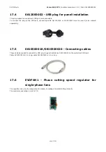
Page 87: ...or 0810500020 must be used to be ordered separately 17 5 0810500018 0810500020 Connecting cables These cables are used to connect the USB plug for panel installation 0812000002 to the controller s USB port Cable 0810500018 is 2 m long cable 0810500020 is 0 5 m long 17 6 EVDFAN1 Phase cutting speed regulator for single phase fans The regulator can vary the evaporator fan speed to manage the blast c...

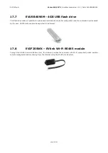
Page 88: ... and download the controller configuration and the customized cycles saved by the user HACCP data can also be exported in CSV format 17 8 EVIF25SWX EVlink Wi Fi RS485 module Through the RS 485 communications port the module provides the controller with Wi Fi connectivity which enables remote management and monitoring from the Internet using the EPoCA cloud system ...

Page 89: ...terface control module Installed from behind using threaded studs On a flat surface with spacers Degree of protection user interface control module IP65 front IP00 Connection methodjgv y96 user interface control module Plug in screw terminal blocks for wires up to 1 5 mm type A female USB connector Plug in screw terminal blocks for wires up to 2 5 mm Maximum permitted length for connecting cablesy...

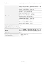
Page 90: ...25 C 77 F Clock battery autonomy in the absence of a power supply 6 months at 25 C 77 F Clock battery charging time 24 h the battery is charged by the power supply of the device Analogue inputs 6 for PTC or NTC probes cabinet probe needle probe with up to 3 sensors evaporator probe and condenser probe PTC probes Sensor type KTY 81 121 990 Ω 25 C 77 F Measurement field from 50 to 150 C from 58 to 3...

Page 91: ...enser fan relay 8 A SPST res 250 VAC Door heater relay 8 A SPDT res 250 VAC Door heater relay 16 A SPST res 250 VAC Auxiliary relay 1 16 A SPST res 250 VAC Auxiliary relay 2 8 A SPST res 250 VAC Auxiliary relay 3 8 A SPST res 250 VAC Type 1 or Type 2 Actions Type 1 Additional features of Type 1 or Type 2 actions C Displays 7 or 5 inch capacitive TFT touch screen graphic display 65K colours 800 x 4...

Page 92: ...EVCO S p A Vcolor 869 879 Installer manual ver 2 2 Code 144VC869E214 page 92 of 94 ...

Page 93: ...bsolutely prohibited unless expressly authorised by EVCO EVCO accepts no liability for the features and technical data described in this document and for any errors it may contain or that can arise from its use EVCO may not be held liable for any damage caused by failure to follow the instructions described in this document EVCO reserves the right to make any modifications to this document without...

Page 94: ...EVCO S p A Vcolor 869 879 Installer manual ver 2 2 Code 144VC869E214 page 94 of 94 EVCO S p A Via Feltre 81 32036 Sedico Belluno ITALIA Tel 0437 8422 Fax 0437 83648 info evco it www evco it ...

Reviews: