EVCO S.p.A.
EVFTFT219 | Installation guide ver. 1.0 | Code 144FTFT219E104
pagina 1 di 50
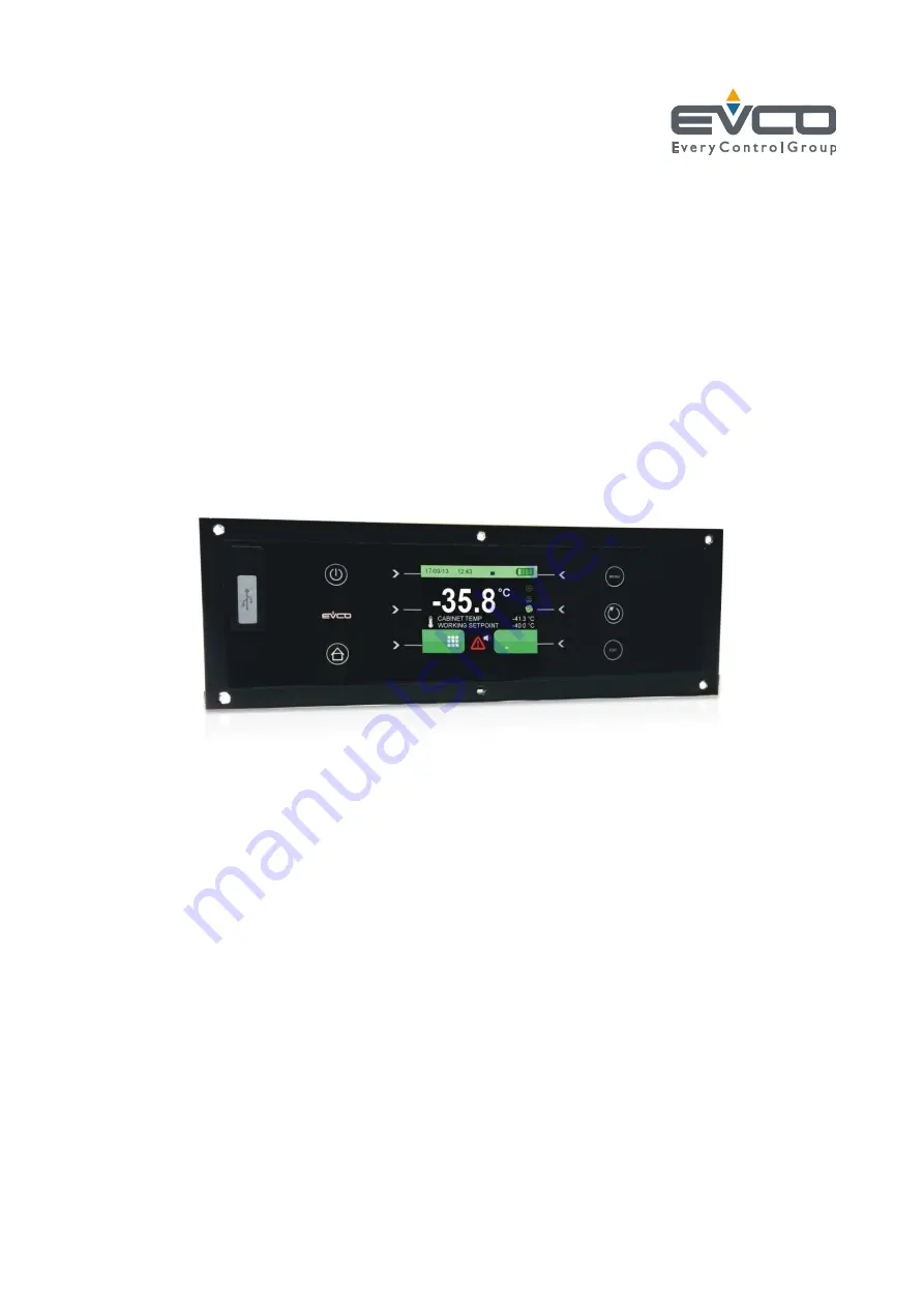
EVFTFT219
Controller
for
laboratory
refrigerated
cabinets, in split version and which can be
integrated into the unit
Installation guide | ENGLISH
Code 144FTFT219E104


