PROGRAMMABLE CONTROLLERS FOR
SINGLE CIRCUIT, DUAL CIRCUIT AND
TRIPLE CIRCUIT
COMPRESSOR PACKS
UP TO 8/12 COMPRESSORS
APPLICATION MANUAL
CODE 144RACKMGE04
Page 1: ...PROGRAMMABLE CONTROLLERS FOR SINGLE CIRCUIT DUAL CIRCUIT AND TRIPLE CIRCUIT COMPRESSOR PACKS UP TO 8 12 COMPRESSORS APPLICATION MANUAL CODE 144RACKMGE04 ...
Page 2: ...ly prior to installation and use and follow all the precautions for installation and electrical connections keep these instructions with the device for future consultation The device must be disposed of in accordance with local regulations pertaining to the collection of electrical and electronic appliances ...
Page 3: ... O expansion unit electrical connections 21 2 7 1 C PRO EXP MEGA electrical connections 21 2 7 2 C PRO EXP GIGA electrical connections 22 2 7 3 Input and output identification tables 23 3 COMPONENT NETWORK AND ACCESSORIES 26 3 1 Example for the C PRO MEGA RACK and C PRO GIGA RACK built in versions 26 3 2 Example for the C PRO MEGA RACK and C PRO GIGA RACK case versions Errore Il segnalibro non è d...
Page 4: ...6 6 3 Fan rotation 91 6 6 4 Protective device timings 92 6 6 5 Safety device inputs 93 6 6 6 Inverter configuration 93 6 7 Miscellaneous controls 94 6 7 1 Inverter configuration compressors fans 94 6 7 2 Compressor time bands 95 6 7 3 Fan time bands 96 6 7 4 Digital input setpoint alteration 97 6 7 5 Supervisor setpoint alteration 97 6 7 6 Manual operation 97 6 7 7 Floating condensation management...
Page 5: ...h safety device is associated with a particular alarm which will be triggered in order to identify the type of fault The outcome of certain alarms will be to shutdown the relevant mechanical devices in order to avoid further faults others will only indicate the fault without having any effect on the operation of the machine The application has a navigable user interface by means of which it is pos...
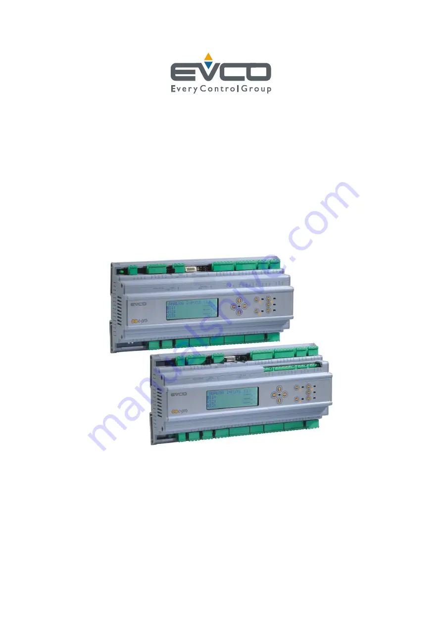
Page 6: ...C PRO MEGA RACK C PRO GIGA RACK APPLICATION MANUAL Page 6 C PRO MEGA ...
Page 7: ...C PRO MEGA RACK C PRO GIGA RACK APPLICATION MANUAL Page 7 C PRO GIGA ...
Page 8: ...l No of analogue outputs 4 2 Application 2 C PRO GIGA RACK for dual circuit control units preset configuration Total No of digital outputs 13 Total No of digital inputs 12 Total No of analogue inputs 8 Total No of analogue outputs 4 3 Application 3 C PRO MEGA RACK C PRO EXP MEGA e g for dual circuit control units Total No of digital outputs 8 8 16 Total No of digital inputs 10 8 18 Total No of ana...
Page 9: ... Application 1 use of the C PRO MEGA RACK single circuit control unit As a preset configuration the C PRO MEGA RACK is configured to manage single circuit compressor packs the services mentioned in the figure below refer specifically to the preset configurations ...
Page 10: ...IGA RACK is pre configured to control dual circuit compressor packs the services mentioned in the figure below refer precisely to the preset configurations Compressors 1 and 2 and related load increments appertain to circuit 1 compressors 3 and 4 and related load increments appertain to circuit 2 Fans 1 and 2 appertain to circuit 1 fans 3 and 4 appertain to circuit 2 ...
Page 11: ...ured to control single circuit compressor packs the services mentioned in the figure below refer to an example of a dual circuit control unit with separate condensation Compressors 1 2 and 3 appertain to circuit 1 compressors 4 5 and 6 appertain to circuit 2 Fans 1 2 and 3 appertain to circuit 1 fans 4 5 and 6 appertain to circuit 2 The C PRO MEGA RACK and C PRO EXP MEGA power supplies must be gal...
Page 12: ...ircuit compressor packs the services mentioned in the figure below refer to an example of a dual circuit control unit with separate condenser where the controller is used with an I O expansion unit Compressors 1 2 and 3 appertain to circuit 1 compressors 4 5 and 6 appertain to circuit 2 Fans 1 2 and 3 appertain to circuit 1 fans 4 5 and 6 appertain to circuit 2 The C PRO GIGA RACK and C PRO EXP GI...
Page 13: ...ATION MANUAL Page 13 2 5 Controller electrical connections The layout relating to the controllers electrical connections is shown below with tables listing the meanings of the inputs and outputs 2 5 1 C PRO MEGA RACK electrical connections ...
Page 14: ...C PRO MEGA RACK C PRO GIGA RACK APPLICATION MANUAL Page 14 2 5 2 C PRO GIGA RACK electrical connections ...
Page 15: ...ue input common ground JE 1 COM digital input common connection JE 2 DI 1 No 1 digital input 12 24 VAC DC JE 3 DI 2 No 2 digital input 12 24 VAC DC JE 4 COM digital input common connection JF 1 COM digital input common connection JF 2 DI 3 No 3 digital input 12 24 VAC DC JF 3 DI 4 No 4 digital input 12 24 VAC DC JF 4 DI 5 No 5 digital input 12 24 VAC DC JF 5 DI 6 No 6 digital input 12 24 VAC DC JF...
Page 16: ... 0 5 10 V 0 20 mA 4 20 mA JM 4 AO 4 No 4 analogue output 0 5 10 V 0 20 mA 4 20 mA JM 5 GND analogue output common ground C2 1 VCC serial port and optoisolated analogue output secondary power supply input 15 VDC C2 2 GND secondary power supply reference VDC 12 5 V Imax 200 mA as the sum of the current for all VDC terminals Card with 24 VAC DC power supply Conn Abbre v Description CA 1 VCC main card...
Page 17: ...l input common connection 230 VAC Second RS 485 port on request Conn Abbre v Description YE 1 RS485 RS 485 connector for connecting to supervision system YE 2 RS485 RS 485 connector for connecting to supervisor system YE 3 GND GND connector for connecting to supervision system via RS485 RS 232 port available on request as an alternative to the second RS 485 port Conn Abbre v Description YF 1 5Vdc ...
Page 18: ...ed Jumper inserted Termination 120 inserted JMP6 Analogue output selection A B C D Jumper A inserted Jumper B inserted Jumper C inserted Jumper D inserted Output AO1 under current Output AO2 under current Output AO3 under current Output AO4 under current A B C D Jumper A not inserted Jumper B not inserted Jumper C not inserted Jumper D not inserted Output AO1 under tension Output AO2 under tension...
Page 19: ... probe Terminal Analogue output Description By default not configured Terminal Digital input Description DI1 No 1 digital input Compressor 1 thermal DI2 No 2 digital input Compressor 2 thermal DI3 No 3 digital input Compressor 3 thermal DI4 No 4 digital input Compressor 4 thermal DI5 No 5 digital input Fan thermal common connection DI6 No 6 digital input Fluid level DI7 No 7 digital input Low pres...
Page 20: ...t Compressor 1 thermal DI 2 No 2 digital input Compressor 2 thermal DI 3 No 3 digital input Compressor 3 thermal DI 4 No 4 digital input Compressor 4 thermal DI 5 No 5 digital input Fan thermal common connection C1 DI 6 No 6 digital input Fan thermal common connection C2 DI 7 No 7 digital input Fluid level C1 DI 8 No 8 digital input Fluid level C2 DI 9 No 9 digital input Low pressure suction press...
Page 21: ... MANUAL Page 21 2 7 I O expansion unit electrical connections The layout relating to the expansion unit electrical connections is shown below with tables listing the meanings of the inputs and outputs 2 7 1 C PRO EXP MEGA electrical connections ...
Page 22: ...C PRO MEGA RACK C PRO GIGA RACK APPLICATION MANUAL Page 22 2 7 2 C PRO EXP GIGA electrical connections ...
Page 23: ... 7 digital input 12 24 VAC DC JG 5 DI8 No 8 digital input 12 24 VAC DC JG 6 COM digital input common connection YA 1 VDC power supply output connector 12 VDC YA 2 CAN1 connector for connecting the CAN serial port CAN YA 3 CAN1 connector for connecting the CAN serial port CAN YA 4 GND power supply output reference connector ground JH 1 NC 1 relay No 1 contact normally closed JH 2 COM 1 relay No 1 c...
Page 24: ...lly open JP 3 COM12 relay No 12 common connection JP 4 NO 12 relay No 12 contact normally open JP 5 COM13 relay No 13 common connection JP 6 NO 13 relay No 13 contact normally open JQ 1 DI9 No 9 digital input 230 VAC JQ 2 DI10 No 10 digital input 230 VAC JQ 3 CONHV digital input common connection 230 VAC Jumper and LED meanings JMP3 CAN terminator Jumper not inserted Termination 120 not inserted J...
Page 25: ...PRO MEGA RACK C PRO GIGA RACK APPLICATION MANUAL Page 25 configuration by simply connecting the network components For further information please refer to the chapter CAN connection in the Hardware Manual ...
Page 26: ...C PRO MEGA RACK C PRO GIGA RACK APPLICATION MANUAL Page 26 3 COMPONENT NETWORK AND ACCESSORIES 3 1 Example ...
Page 27: ...nd RIGHT displays the screens in succession ENTER confirms the value displayed in editing mode otherwise it runs any commands associated with the text at the cursor point If pressed for approx 2 seconds while viewing an alarm page it allows the alarm to be reset If viewing the alarm pages each press scrolls through the active alarms ESC cancels the present value if in editing mode otherwise it rec...
Page 28: ...ched off by digital input Flashing rapidly machine switched off by supervisor system 4 2 Page list This section will introduce the application s main pages and menus As already mentioned the main menu is subdivided into four levels user service installer and system builder plus a menu for managing the functions associated with the system clock and certain free access pages The menu structure is as...
Page 29: ...current page then after 4 minutes the inserted password expires and it is necessary to insert it once more Clock menu This menu contains the functions associated with the system RTC setting the clock enabling the compressor fan time bands setting the time bands setting the offsets to the main setpoints for each time band This menu is not password protected and may be accessed by pressing the K2 ke...
Page 30: ... which menu to move by moving the screen highlight above the indicators and pressing the ENTER key for conformation Pressing the ESC key within this menu returns to the default start page if the machine is on or the OFF page if the machine is switched off User menu The user menu is a level 1 menu i e it is necessary to insert the user level password or higher in order to be able to view modify the...
Page 31: ... fan operation For example the operation times the status of the relevant alarms and the maximum acceptable time threshold In the MANUAL menu it is possible to manually automatically set the compressors and fans and whether outputs can be forced in order to test functionality In the I O STATUS menu it is possible to view all the properties involved with the application inputs and outputs digital i...
Page 32: ...eset type The MISCELLANEOUS menu contains other general parameters full scale values for the transducers Modbus communication activations On Off temperature probe activation digital input and supervisor system secondary setpoint activation analogue input type refrigerant gas when using temperature probes suction line compensation password From the DEFAULTS menu it is possible to restore the defaul...
Page 33: ...ut position Such characteristics are collected in a separate submenu in order to distinguish compressors fans and safety devices Setting the positions of the various alarm inputs also enables their operation Indeed an alarm is only enabled if the parameter identifying its physical position on the terminal is set and is other than zero If it is desired not to use an alarm simply leave the correspon...
Page 34: ...eric display and will not be editable This feature makes configuration maintenance and use of the machine simpler During configuration once the system type and characteristics are selected the unused parameters will no longer be accessible During maintenance it will be possible to test the functions of the devices effectively configured in the system During normal use the number of parameters and ...
Page 35: ...ystem builder menu hardware branch o CO Pa installer menu parameters branch Parameters table Code Parameter Description Default Min Max Uo M Menu Notes CLOCK MENU PARAMETERS Time band management PT00 Enable compressor time bands Enables compressor time band management NO NO 0 YES 1 OR PT01 04 Comp time band 1 4 Sets the four compressor time bands OR PT11 14 Compressor time band offset 1 4 Circuit ...
Page 36: ...offset value for use of secondary setpoint from the compressor digital input 0 0 20 0 20 0 Bar UT Visible if PG01 1 PUC5 Comp sup Secondary setpoint offset Circuit 2 Sets the offset value for use of secondary setpoint from compressor supervisor 0 0 20 0 20 0 Bar UT Visible if PG01 1 SPC3 Compressor setpoint Circuit 3 Sets the setpoint value for the compressor suction probe 1 0 PC52 PC53 Bar UT Vis...
Page 37: ...ERS PM00 Compressor operational time alarm threshold Sets the maximum compressor operation time limit Beyond this limit the relevant alarm will be tripped 20000 0 500000 Hou rs MA F PM01 10 Compressor operation time 1 10 Operation times for each compressor 0 0 500000 Hou rs MA F Compressors 1 to 10 Visibility PM31 PM32 Compressor operation time 11 12 Operation times for each compressor 0 0 500000 ...
Page 38: ...Enables manual automatic operation of each fan M manual A normal operation A A 0 M 1 MA M Fans 1 to 10 Visibility PM61 70 Fan forcing 1 10 In manual operation this forces the fans to be switched on and off S fan off A fan on S S 0 A 1 MA M Fans 1 to 10 Visibility PM73 PM74 Enable fan 11 12 Enables manual automatic operation of each fan M manual A normal operation A A 0 M 1 MA M Fans 11 and 12 Visi...
Page 39: ... regulation of circuit 1 compressors 600 0 999 Sec IS RC Visible if PC14 0 PC17 Compressor proportional band Circuit 1 Proportional band Bp for side band regulation of circuit 1 compressors 0 5 0 20 0 Bar IS RC Visible if PC14 0 PC18 Comp zone Circuit 1 Zone value for neutral zone regulation of circuit 1 compressors 0 5 0 20 0 Bar IS RC Visible if PC14 1 PC19 Comp zone differential Circuit 1 Diffe...
Page 40: ...Bar IS RC Visible if PG01 1 and PG34 1 PC39 Comp zone differential Circuit 2 Differential for neutral zone regulation within which the calculation for the insertion release time of the subsequent step varies Circuit 2 0 5 0 20 0 Bar IS RC Visible if PG01 1 and PG34 1 PC40 Compressor TOnMin Circuit 2 Minimum insertion time for subsequent compressor step circuit 2 neutral zone reg 20 0 PC41 Sec IS R...
Page 41: ... Neutral Zone 1 Side Band 0 Neutral Zone 1 IS RC Visible if PG01 2 PC56 Compressor integral time Circuit 3 Integral time Ti for side band regulation of circuit 3 compressors 600 0 999 Sec IS RC Visible if PG01 2 and PC54 0 PC57 Compressor proportional band Circuit 3 Proportional band Bp for side band regulation of circuit 3 compressors 0 5 0 20 0 Bar IS RC Visible if PG01 2 and PC54 0 PC58 Comp zo...
Page 42: ...pressor inverter SP offset Circuit 3 Suction setpoint offset for circuit 3 inverter regulation of the compressor 0 0 20 0 20 0 Bar IS RC Visible if PG01 2 and PG22 1 PC66 Inverter comp min Circuit 3 Minimum compressor value with circuit 3 inverter 0 0 0 0 100 0 IS RC Visible if PG01 2 and PG22 1 PC67 Inverter comp speedup Circuit 3 Compressor speedup time with circuit 3 inverter 0 0 999 Sec IS RC ...
Page 43: ...ween switching off of increments 20 0 999 Sec IS C PC11 Comp probe error Circuit 1 Number of compressors that will be forced if an alarm occurs on the circuit 1 suction probe 1 0 PG11 IS C PC31 Comp probe error Circuit 2 Number of compressors that will be forced if an alarm occurs on the circuit 2 suction probe 1 0 PG15 IS C Visible if PG01 1 PC51 Comp probe error Circuit 3 Number of compressors t...
Page 44: ...3 1 Visibility PC84 Comp 4 power Compressor 4 power output 1 0 5000 kW IS C Visible if PG03 1 Visibility PC85 Comp 5 power Compressor 5 power output 1 0 5000 kW IS C Visible if PG03 1 Visibility PC86 Comp 6 power Compressor 6 power output 1 0 5000 kW IS C Visible if PG03 1 Visibility PC87 Comp 7 power Compressor 7 power output 1 0 5000 kW IS C Visible if PG03 1 Visibility PC88 Comp 8 power Compres...
Page 45: ...gulation of the fan 0 0 20 0 20 0 Bar IS RF Visible if PG42 1 PF26 Fan inverter minimum Circuit 1 Minimum fan value with circuit 1 inverter 0 0 0 0 100 0 IS RF Visible if PG42 1 PF27 Fan inverter speedup Circuit 1 Fan speedup time with circuit 1 inverter 2 0 999 Sec IS RF Visible if PG42 1 PF28 Fan inverter time Circuit 1 Inverter ramp Time taken for the inverter to go from the minimum value to th...
Page 46: ...the inverter to go from the minimum value to the maximum value circuit 2 neutral zone reg 10 0 999 Sec IS RF Visible if PG01 1 and PG30 0 and PG46 1 PF52 Fan min setpoint Circuit 3 Minimum supply setpoint value pertaining to the circuit 3 fans 1 0 PH03 SPF3 Bar IS RF Visible if PG01 2 and PG30 0 PF53 Fan max setpoint Circuit 3 Maximum supply setpoint value pertaining to the circuit 3 fans 25 0 SPF...
Page 47: ...f PG01 2 and PG30 0 and PG52 1 PF01 Fan rotation Type of rotation used for fan management 0 FIFO 1 LIFO 2 FIFO time 3 LIFO time FIFO FIFO 0 LIFO time 3 IS F PF02 Enable compressor regulation If enabled allows selection of fan regulation only if at least one compressor is on NO NO 0 YES 1 IS F PF07 TOnOther Minimum time that must elapse before another fan can be switched on 2 0 999 Sec IS F PF08 TO...
Page 48: ...e minimum full scale value for the supply probe 0 0 10 0 PH04 Bar IS V PH04 Maximum full scale supply Sets the maximum full scale value for the supply probe 30 0 PH03 45 0 Bar IS V PH05 System ON OFF from keypad Enables switching the machine on off by pressing the ESC key YES NO 0 YES 1 IS V PH06 Circuit ON OFF from keypad Enables switching circuits on off by pressing the relevant key NO NO 0 YES ...
Page 49: ...ntact NO NO 0 NC 1 IS V PH23 Enable environment temp probe Enables the probe AI07 for measuring environment temperature NO NO 0 YES 1 IS V PH24 Enable external temp probe Enables the probe AI08 for measuring the external temperature NO NO 0 YES 1 IS V PH25 Enable secondary setpoint from DI Enables the secondary setpoint function from the digital input NO NO 0 YES 1 IS V PH26 Enable secondary setpo...
Page 50: ...C PRO MEGA RACK C PRO GIGA RACK APPLICATION MANUAL Page 50 compensation line neutral zone 0 NO 1 YES ...
Page 51: ...PG01 1 PH47 AI5_6 probe type Sets analogue input type for AI05 and AI06 2 NTC 3 0 20mA 4 4 20mA 4 4 20mA 2 4 IS V Visible if PG01 2 PH53 Buzzer enable Enables the buzzer to sound YES 1 NO 0 YES 1 IS V PSd3 Installer PSd Installer level password 0 999 9999 IS V ALARM PARAMETERS PH17 DI alarm logic Sets the digital input alarm logic used for controlling the alarms 0 Normally open NO 1 Normally close...
Page 52: ...pressor thermal alarm reset type M A 0 M 1 IS S M manual A automatic PA13 Comp pressure switch alarm reset Sets the compressor pressure switch alarm reset type M A 0 M 1 IS S M manual A automatic PA14 Oil diff alarm reset Sets the compressor oil differential alarm reset type M A 0 M 1 IS S M manual A automatic PA23 Fan thermal alarm reset Sets the fan thermal alarm reset type M A 0 M 1 IS S M manu...
Page 53: ...e if PG01 1 and PG30 0 PA31 C2 supply HP alarm setpoint Circuit 2 supply probe high pressure alarm setpoint 20 0 PA29 PH04 Bar IS S Visible if PG01 1 and PG30 0 PA32 Circuit 2 supply HP alarm diff Circuit 2 supply probe high pressure alarm differential 1 0 0 0 20 0 Bar IS S Visible if PG01 1 and PG30 0 PA35 C3 suction LP alarm setpoint Circuit 3 suction probe low pressure alarm setpoint 0 5 PH01 P...
Page 54: ...K PG02 Enable expansion Enables the expansion unit and the corresponding alarms NO NO 0 YES 1 CO W PG03 Enable differently powered compressors Enables the management of compressors with different nominal power ratings NO NO 0 YES 1 CO W PG04 Number of increments per compressor Sets the number of increments for each compressor 1 0 3 CO W Default 0 on C PRO MEGA RACK PG05 Number of safety devices pe...
Page 55: ... Circuit 3 Sets the number of fans for circuit 3 0 0 12 CO W Max 8 on C PRO MEGA RACK Visible if PG01 2 and PG30 0 PG52 Circuit 3 fan inverter enable Enables the fan with circuit 3 inverter NO NO 0 YES 0 CO W Visible if PG01 2 and PG30 0 PH20 Circuit 1 system type or control unit type Sets the type of control unit for the first circuit 0 1 BT 2 TN 3 AT 0 AT 3 CO Pa In the case of a single circuit ...
Page 56: ...sition Sets the position of the increment 1 digital output for compressor 2 4 0 13 26 CO Hw Default 0 Max 8 16 on C PRO MEGA RACK Visibility HC22 C2 increment 2 DO position Sets the position of the increment 2 digital output for compressor 2 0 0 13 26 CO Hw Max 8 16 on C PRO MEGA RACK Visibility HC32 C2 increment 3 DO position Sets the position of the increment 3 digital output for compressor 2 0 ...
Page 57: ...ity HC25 C5 increment 2 DO position Sets the position of the increment 2 digital output for compressor 5 0 0 13 26 CO Hw Max 8 16 on C PRO MEGA RACK Visibility HC35 C5 increment 3 DO position Sets the position of the increment 3 digital output for compressor 5 0 0 13 26 CO Hw Max 8 16 on C PRO MEGA RACK Visibility HC06 Compressor C6 DO position Sets the position of the digital output for compresso...
Page 58: ...0 0 13 26 CO Hw Max 8 16 on C PRO MEGA RACK Visibility HC09 Compressor C9 DO position Sets the position of the digital output for compressor 9 Or compressor inverter consent position 0 0 13 26 CO Hw Max 8 16 on C PRO MEGA RACK Visibility HC19 C9 increment 1 DO position Sets the position of the increment 1 digital output for compressor 9 0 0 13 26 CO Hw Max 8 16 on C PRO MEGA RACK Visibility HC29 C...
Page 59: ...sition of the digital output for compressor 12 Or compressor inverter consent position 0 0 13 26 CO Hw Max 8 16 on C PRO MEGA RACK Visibility HC61 C12 increment 1 DO position Sets the position of the increment 1 digital output for compressor 12 0 0 13 26 CO Hw Max 8 16 on C PRO MEGA RACK Visibility HC62 C12 increment 2 DO position Sets the position of the increment 2 digital output for compressor ...
Page 60: ... digital output for fan 9 Or fan inverter consent position 0 0 13 26 CO Hw Max 8 16 on C PRO MEGA RACK Visibility HF10 Fan 10 DO position Sets the position of the digital output for fan 10 Or fan inverter consent position 0 0 13 26 CO Hw Max 8 16 on C PRO MEGA RACK Visibility HF11 Fan 11 DO position Sets the position of the digital output for fan 11 Or fan inverter consent position 0 0 13 26 CO Hw...
Page 61: ...tion pressure switch low pressure alarm digital input 9 0 12 22 CO Hw Default 7 Max 10 18 on C PRO MEGA RACK Hd14 C1 supply HP alarm DI pos Sets the position of the circuit 1 supply pressure switch high pressure alarm digital input 11 0 12 22 CO Hw Default 8 Max 10 18 on C PRO MEGA RACK Hd15 C1 comp oil diff alarm DI pos Sets the position of the circuit 1 compressor oil differential alarm digital ...
Page 62: ...s the position of the circuit 3 fluid level alarm digital input 0 0 12 22 CO Hw Max 10 18 on C PRO MEGA RACK Visible if PG01 2 Hd33 C3 suction LP alarm DI pos Sets the position of the circuit 3 suction pressure switch low pressure alarm digital input 0 0 12 22 CO Hw Max 10 18 on C PRO MEGA RACK Visible if PG01 2 Hd34 C3 supply HP alarm DI pos Sets the position of the circuit 3 supply pressure swit...
Page 63: ...al alarm digital input 0 0 12 22 CO Hw Max 10 18 on C PRO MEGA RACK Visibility Hd46 Comp 6 thermal DI pos Sets the position of the compressor 6 thermal alarm digital input 0 0 12 22 CO Hw Max 10 18 on C PRO MEGA RACK Visibility Hd47 Comp 7 thermal DI pos Sets the position of the compressor 7 thermal alarm digital input 0 0 12 22 CO Hw Max 10 18 on C PRO MEGA RACK Visibility Hd48 Comp 8 thermal DI ...
Page 64: ...22 CO Hw Max 10 18 on C PRO MEGA RACK Visibility Hd61 Compressor 1 pressure switch DI pos Sets the position of the compressor 1 pressure switch alarm digital input 0 0 12 22 CO Hw Max 10 18 on C PRO MEGA RACK Visibility Hd62 Compressor 2 pressure switch DI pos Sets the position of the compressor 2 pressure switch alarm digital input 0 0 12 22 CO Hw Max 10 18 on C PRO MEGA RACK Visibility Hd63 Comp...
Page 65: ...il differential alarm digital input 0 0 12 22 CO Hw Max 10 18 on C PRO MEGA RACK Visibility Hd72 Compressor 2 oil diff DI pos Position of the compressor 2 oil differential alarm digital input 0 0 12 22 CO Hw Max 10 18 on C PRO MEGA RACK Visibility Hd73 Compressor 3 oil diff DI pos Position of the compressor 3 oil differential alarm digital input 0 0 12 22 CO Hw Max 10 18 on C PRO MEGA RACK Visibil...
Page 66: ... alarm digital input 0 0 12 22 CO Hw Max 10 18 on C PRO MEGA RACK Visibility Hd83 Fan 3 thermal DI pos Sets the position of the fan 3 thermal alarm digital input 0 0 12 22 CO Hw Max 10 18 on C PRO MEGA RACK Visibility Hd84 Fan 4 thermal DI pos Sets the position of the fan 4 thermal alarm digital input 0 0 12 22 CO Hw Max 10 18 on C PRO MEGA RACK Visibility Hd85 Fan 5 thermal DI pos Sets the positi...
Page 67: ...gital input 0 0 12 22 CO Hw Max 10 18 on C PRO MEGA RACK Visibility Hd92 Fan 12 thermal DI pos Sets the position of the fan 12 thermal alarm digital input 0 0 12 22 CO Hw Max 10 18 on C PRO MEGA RACK Visibility Once machine parameters are configured and every time configuration parameters are modified it is recommended the system be switched off and restarted in order to allow the card to configur...
Page 68: ...robe AI 7 Environment temperature Environment temperature Environment temperature Environment temperature Environment temperature Probe AI 8 External temperature External temperature External temperature External temperature External temperature Analogue output AO 1 Compressor with inverter Compressor with inverter C1 Compressor with inverter C1 Compressor Fan with inverter C1 Compressor Fan with ...
Page 69: ...the remote On Off contact if all other enabled conditions are present the machine or individual circuit will be switched ON Machine circuit off if the remote On Off contact is open the machine or individual circuit is switched OFF by digital input indicated by the wording OFF_D for the individual circuit status 3 By means of the supervision protocol parameter enabled function Machine circuit on ac...
Page 70: ...ed to the ON state if fulfilling the OFF by supervisor conditions and the OFF by digital input condition is not met The machine On Off key is the ESC key pressed for approx 2 seconds The remote On Off inputs if present are configured by means of the relevant parameters ...
Page 71: ... are as follows Integral time IT Proportional band PB Side band suction SetPoint SP The above figure shows the behaviour of band regulation SP SP PB Depending on the suction pressure value regulation adds or removes the number of steps to request from the compressors Under such regulation the band is displaced above the setpoint It is possible to select whether control will refer to PI or just P r...
Page 72: ...occurs with reduced frequency or reduced compressor start ups to the benefit of the mechanical lifespan of the same 6 3 2 Neutral zone regulation This type of regulation envisages the definition of a neutral zone within which no activation or deactivation decision will be taken i e startup operations will not be requested for any of the devices The parameters defining this regulation are as follow...
Page 73: ... control and in order to do this it is essential to set several parameters relating to the inverter device it is intended to use in addition to enabling its use The parameters in question are the following Inverter differential ID Inverter enabling Inverter offset with respect to the suction setPoint OFSI Minimum inverter value MinI SpeedUp time Side band suction SetPoint SP The regulator output w...
Page 74: ...er This type of control introduces inverter control to normal neutral zone control and in order to do this it is essential to set several parameters relating to the inverter device it is intended to use in addition to enabling its use The parameters in question are the following Inverter enabling Minimum inverter value MinI Inverter time IT SpeedUp time neutral zone suction setPoint Regulation var...
Page 75: ...s required having completed the request in the case where the off zone remains the inverter value is restored to the maximum value and the cycle restarted once more If the switch off request remains ongoing one or all of the compressors are switched off and the inverter value finally reaches zero In the case where the parameter MinI has been set then with each switching on the inverter will mainta...
Page 76: ... and the corresponding operation alarms are correctly assigned on the basis of the above guidelines Please note By enabling the inverter for compressor regulation the FIRST compressor for each circuit will be the one controlled by the inverter while any other additional compressors will be hermetic in nature without increment functionality and will be controlled by digital outputs using relays 6 4...
Page 77: ...s altering the switch on and switch off sequence Rotation type is set by means of the parameter Compressor Rotation PC01 The program can manage 4 types of rotation FIFO LIFO FIFO time LIFO time 1 FIFO This follows First In First Out logic i e the first compressor switched on will be the first switched off Initially this logic might leads to a large difference in operational hours between the vario...
Page 78: ...rating hours for each compressor Startup will switch on the compressor with the least operating hours while shut down will switch off the compressor with the most operating hours In the case where a selection must be made between compressors with the same number of hours then a LIFO rotation is implemented so as to thus guarantee rotation of the configured compressors Example 1 Switch on C1 3 hour...
Page 79: ...outputs dedicated to incrementing If set to NC the outputs will be normally energised closed and will be opened in order to request greater power Copeland type logic If set to NO the outputs will be normally de energised open and will be closed in order to request greater power Feeders type logic Switching on off mode In the case where incremented compressors are being used this parameter PC02 all...
Page 80: ...protect the mechanical devices from the various startup operations to which they are subjected TMinOn Minimum compressor switch on time PC04 Once activated the compressor will remain on for this amount of time before being able to be switched off TMinOff Minimum compressor switch off time PC05 Minimum elapsed time since the last switch off before the compressor can be switched on once more TOnOn M...
Page 81: ...ameter safety device type PH16 the appropriate combination for the application can be selected The three safety devices managed are as follows Compressor thermal Compressor oil differential Compressor high low pressure pressure switch The four combinations implemented are described in the following table Parameter Type Delay Reset 0 None 1 Thermal Configurabl e Configurabl e Thermal Configurabl e ...
Page 82: ... logic 1 circuit The inverter if enabled is virtually the compressor 1 is necessary to configure the parameter of the first compressor then must be always configured the parameter HC01 2 circuits The inverter of circuit 1 if enabled is virtually the compressor 1 then must be configured the parameter HC01 the inverter of circuit 2 if enabled is virtually the first compressor after the circuit 1 com...
Page 83: ...nt parameter enable compressors of different nominal power PG03 and set the parameters representing the nominal power for each of the compressors to be used in the system The software calculates the maximum power that can be expressed by the individual nominal power ratings of each of the compressors and on the basis of the requests from the regulators calculates the best combination of compressor...
Page 84: ...city in order to compensate for the increased pressure loss along the suction line In practice the services which should operate at constant evaporation pressure are forced to operate higher pressures when the cold requirement is greater and vice versa This means that in order to guarantee cold production at the desired temperature even with loads approaching the nominal values it is necessary to ...
Page 85: ...possible with incrementable circuits with at least two compressors or with one compressor with incrementing devices The parameters pertaining to this function are as follows PC70 Enable high pressure incrementing PC71 Condensation pressure switch control setpoint limit Circuit 1 PC72 Condensation pressure switch control setpoint limit Circuit 2 PC73 Condensation pressure switch control setpoint li...
Page 86: ...ion the band is displaced above the setPoint It is possible to select whether control will refer to PI or just P regulation by either setting the parameter for integral action namely the integration time Ti or otherwise In the specific case where this parameter is set to the value zero regulation is proportional only otherwise it is also integral Ti corresponds to the time necessary for integral a...
Page 87: ...s prior to being fulfilled While in the case of the switch on zone each switch on request will have to wait NZ_TOn seconds prior to being fulfilled 6 5 3 Side band regulation with inverter This type of control introduces inverter control to normal side band control and in order to do this it is essential to set several parameters relating to the inverter device it is intended to use in addition to...
Page 88: ... on the first fan Below is given an example of how to change regulation with the presence of an inverter 6 5 4 Neutral zone regulation with inverter This type of control introduces inverter control to normal neutral zone control and in order to do this it is essential to set several parameters relating to the inverter device it is intended to use in addition to enabling its use The parameters in q...
Page 89: ...s described by said parameter each time the regulation switches from the neutral zone to the switch on zone Below is an example of a graph for the switch on zone of how regulation varies depending on whether the fan is configured with an inverter or otherwise 6 5 5 Unique condensation dual triple circuits only Unique condensation allows the fan process to be executed using a single circuit By sett...
Page 90: ...s Indeed the circuit is unique Dual circuit and triple circuit The sum of the fans used in the two three circuits including the inverters must not exceed 12 8 if using C PRO MEGA which is the maximum number of fans managed by the program The digital outputs and inputs assigned to the fans and the corresponding operation alarms are correctly assigned on the basis of the above guidelines In the case...
Page 91: ...ate or operating manually will be inserted at the top of the list of compressors to be switched on They will have maximum priority with respect to the other compressors altering the switch on and switch off sequence Rotation type is set by means of the parameter Fan Rotation PF01 The program can manage 4 types of rotation FIFO LIFO FIFO time LIFO time 1 FIFO This follows First In First Out logic i...
Page 92: ...hours F4 5 hours Switch off F4 5 hours F2 3 hours F3 3 hours F1 1 hour Time based rotation seeks to balance the number of operating hours of the fans present in the system 4 LIFO time of operation This rotation favours comparing the operating times of the various fans During startup the fan with the least operating hours will be favoured while shut down will favour the fan with the most operating ...
Page 93: ...hermal alarms besides setting the relevant parameter it is also essential to set the positions where the digital inputs pertaining to the various selected fans will be connected from within the System builder Hardware menu Where there is no desire to set an alarm simply set the parameter to the value zero 6 6 6 Inverter configuration For each inverter used must be selected a position of the digita...
Page 94: ...iguration parameters CircuitNumber 1 Enable Circuit 1 Compressor Inverter YES Number of Compressors for Circuit 1 6 Number of Compressor Steps 0 Enable Circuit 1 Fan Inverter NO Number of Fans for Circuit 1 3 Example 2 configuration parameters CircuitNumber 1 Enable Circuit 1 Compressor Inverter NO Number of Compressors for Circuit 1 5 Number of Compressor Steps 2 Enable Circuit 1 Fan Inverter NO ...
Page 95: ...utomatically sum the circuit offsets to the suction setpoint outwith the selected bands the setpoint will remain at the value set by the parameter Time band configuration is based on 4 parameters different for each circuit for the setpoint offsets and an additional four parameters general for the time band settings Time band 1 start Circuit band 1 offset 1 2 3 Time band 2 start Circuit band 2 offs...
Page 96: ... band on the basis of the current time the program will automatically sum the circuit offsets to the supply setpoint outwith the selected bands the setpoint will remain at the value set by the parameter Time band configuration is based on 4 parameters different for each circuit for the setpoint offsets and an additional four parameters general for the time band settings Time band 1 start Circuit b...
Page 97: ...et by the supervision protocol different for compressors and fans sum the adjusted offset to the main setpoint in order to allow variation To set this function it is necessary to configure the parameter supervisor secondary setpoint enabling PH26 and the status enable by means of the exported variable If this value is not set the function will remain disabled 6 7 6 Manual operation The program all...
Page 98: ...cedure it is necessary to set the correct compressor to manual depending on how the system has been configured Once manual enabling has been correctly set it is possible to force with a value of between 0 0 and 100 0 the inverter for each circuit by means of the parameters circuit 1 circuit 2 circuit 3 compressor inverter forcing circuit 1 circuit 2 circuit 3 fan inverter forcing present in the se...
Page 99: ...ice Operation menu there is a page offering the option to store the date of the most recent system maintenance By pressing Update the old date will be automatically set to the current date thus also updating the parameter PM90 representing precisely the last maintenance date 6 7 10 Restore default parameters By means of the Restore parameters procedure it is possible to restore all system paramete...
Page 100: ...form the user that alarm pages are being displayed on one of the two interfaces the L0 LED flashes rapidly To exit from management of one view and move to another exit from the alarm pages press the ESC key or this will occur after 60 seconds if no other keys have been pressed Exiting an alarm page by pressing the ESC key or by waiting 60 seconds for timeout returns the user to the main page of th...
Page 101: ...uses for the tripping of the alarm are resolved To silence the buzzer simply press the K0 key 7 2 Alarm table A list of all the alarms managed by the application is given below The order of presentation is the same as the order with which the alarms appear when active Code Alarm description Type Consequence Notes EN01 Expansion unit communication error Auto Display Configurable delay Only present ...
Page 102: ... delay AC32 Compressor 12 thermal Settable Comp 12 OFF Configurable delay AC41 Compressor 1 high low pressure pressure switch Settable Comp 1 OFF AC42 Compressor 2 high low pressure pressure switch Settable Comp 2 OFF AC43 Compressor 3 high low pressure pressure switch Settable Comp 3 OFF AC44 Compressor 4 high low pressure pressure switch Settable Comp 4 OFF AC45 Compressor 5 high low pressure pr...
Page 103: ...operating time Manual Display AF03 Fan 3 operating time Manual Display AF04 Fan 4 operating time Manual Display AF05 Fan 5 operating time Manual Display AF06 Fan 6 operating time Manual Display AF07 Fan 7 operating time Manual Display AF08 Fan 8 operating time Manual Display AF09 Fan 9 operating time Manual Display AF10 Fan 10 operating time Manual Display AF11 Fan 11 operating time Manual Display...
Page 104: ...comp OFF AL23 C3 suction low pressure pressure switch Auto All comp OFF Only present if the circuit is on AL63 C3 fluid level Manual Display Configurable delay ACC3 C3 common oil differential Settable Display Configurable delay AFC3 C3 common fan thermal Manual Display ES07 Faulty or disconnected environment probe Auto Display ES08 Faulty or disconnected external probe Auto Floating condensation O...
Page 105: ...C PRO MEGA RACK C PRO GIGA RACK APPLICATION MANUAL Page 105 By means of the relevant parameter PH18 it is possible to establish the polarity NO or NC of the various alarm digital outputs ...
Page 106: ...O17 Bit2 DO18 Bit10 DO26 R W 513 AI01_Pressure_SuctionC1 R W 514 AI02_Pressure_SupplyC1 R W 515 AI03_Pressure_SuctionC2 R W 516 AI04_Pressure_SupplyC2 R W 517 AI05_Pressure_SuctionC3 R W 518 AI06_Pressure_SupplyC3 R W 519 AI07_EnvironmentProbe R W 520 AI08_ExternalProbe R W 641 AO01_Inv_Circuit1 0 00 100 00 R O 642 AO2_Inv_Circuit2 0 00 100 00 R O 643 AO3_Inv_Circuit3 0 00 100 00 R O 644 AO4_FanIn...
Page 107: ...76 PackedAlarmW8 0 0 65535 Bit1 AL62 Bit2 AL42 Bit3 AL32 Bit4 AL47 Bit5 AL37 Bit6 AL22 Bit7 AL12 Bit8 ACC2 Bit9 AFC2 R W 777 PackedAlarmW9 0 0 65535 Bit1 AL63 Bit2 AL43 Bit3 AL33 Bit4 AL48 Bit5 AL38 Bit6 AL23 Bit7 AL13 Bit8 ACC3 Bit9 AFC3 R W 1025 OnOffBySuperv 0 0 1 R W 1026 OnOffBySuperv_Circuit1 0 0 1 R W 1027 EnSecSP_bySup_Cmp_Circuit1 0 0 1 R W 1028 EnSecSP_bySup_Fan_Circuit1 0 0 1 R W 1029 O...
Page 108: ... 625 5 R W 1303 PowerRequested_Circuit3 0 0 100 R W 1304 PowerSupplied_Circuit3 0 0 100 R W 1537 PT00_Cmp_EnableTimeBands 0 0 1 R W 1538 PT01_Cmp_startTB1 Low 0 0 86399 R W 1539 PT01_Cmp_startTB1 High 1540 PT02_Cmp_startTB2 Low 0 0 86399 R W 1541 PT02_Cmp_startTB2 High 1542 PT03_Cmp_startTB3 Low 0 0 86399 R W 1543 PT03_Cmp_startTB3 High 1544 PT04_Cmp_startTB4 Low 0 0 86399 R W 1545 PT04_Cmp_startT...
Page 109: ...90 0 290 0 R W 1576 PT82_Fan_TBOffset2_Circuit3 0 0 290 0 290 0 R W 1577 PT83_Fan_TBOffset3_Circuit3 0 0 290 0 290 0 R W 1578 PT84_Fan_TBOffset4_Circuit3 0 0 290 0 290 0 R W 1579 SPC1_Cmp_SetPoint_Circuit1 1 0 145 0 625 5 R W 1580 PUC1_Cmp_SecSPOffset_ByDI_Circuit1 0 0 290 0 290 0 R W 1581 PUC4_Cmp_SecSPOffset_BySup_Circuit1 0 0 290 0 290 0 R W 1582 SPC2_Cmp_SetPoint_Circuit2 1 0 145 0 625 5 R W 1...
Page 110: ...611 PM01a10_31_32_V_HoursCmp 6 Low 0 0 500000 R W 1612 PM01a10_31_32_V_HoursCmp 6 High 1613 PM01a10_31_32_V_HoursCmp 7 Low 0 0 500000 R W 1614 PM01a10_31_32_V_HoursCmp 7 High 1615 PM01a10_31_32_V_HoursCmp 8 Low 0 0 500000 R W 1616 PM01a10_31_32_V_HoursCmp 8 High 1617 PM01a10_31_32_V_HoursCmp 9 Low 0 0 500000 R W 1618 PM01a10_31_32_V_HoursCmp 9 High 1619 PM01a10_31_32_V_HoursCmp 10 Low 0 0 500000 R...
Page 111: ...verter_C3 0 00 0 00 100 00 R W 1650 PM40_Fan_LimitHours Low 20000 0 500000 R W 1651 PM40_Fan_LimitHours High 1652 PM41a50_71_72_V_HoursFan 0 Low 0 0 500000 R W 1653 PM41a50_71_72_V_HoursFan 0 High 1654 PM41a50_71_72_V_HoursFan 1 Low 0 0 500000 R W 1655 PM41a50_71_72_V_HoursFan 1 High 1656 PM41a50_71_72_V_HoursFan 2 Low 0 0 500000 R W 1657 PM41a50_71_72_V_HoursFan 2 High 1658 PM41a50_71_72_V_HoursF...
Page 112: ..._Fan 10 0 0 1 R W 1687 PM51a60_73_74_En_Manual_Fan 11 0 0 1 R W 1688 PM61a70_75_76_ForzFans 0 0 0 1 R W 1689 PM61a70_75_76_ForzFans 1 0 0 1 R W 1690 PM61a70_75_76_ForzFans 2 0 0 1 R W 1691 PM61a70_75_76_ForzFans 3 0 0 1 R W 1692 PM61a70_75_76_ForzFans 4 0 0 1 R W 1693 PM61a70_75_76_ForzFans 5 0 0 1 R W 1694 PM61a70_75_76_ForzFans 6 0 0 1 R W 1695 PM61a70_75_76_ForzFans 7 0 0 1 R W 1696 PM61a70_75_...
Page 113: ...xSetPoint_Circuit1 2 5 145 0 625 5 R W 1726 PC14_Cmp_RegulationType_Circuit1 1 0 1 0 Side band 1 Neutral zone R W 1727 PC16_Cmp_PI_Ti_Circuit1 600 0 999 R W 1728 PC17_Cmp_PI_Diff_Circuit1 0 5 0 0 290 0 R W 1729 PC18_Cmp_NZ_Zone_Circuit1 0 5 0 0 290 0 R W 1730 PC19_Cmp_NZ_DiffOutZone_Circuit1 0 5 0 0 290 0 R W 1731 PC20_Cmp_NZ_TOnMin_Circuit1 20 0 999 R W 1732 PC21_Cmp_NZ_TOnMax_Circuit1 60 0 999 R...
Page 114: ... 625 5 R W 1760 PC54_Cmp_RegulationType_Circuit3 1 0 1 0 Side band 1 Neutral zone R W 1761 PC56_Cmp_PI_Ti_Circuit3 600 0 999 R W 1762 PC57_Cmp_PI_Diff_Circuit3 0 5 0 0 290 0 R W 1763 PC58_Cmp_NZ_Zone_Circuit3 0 5 0 0 290 0 R W 1764 PC59_Cmp_NZ_DiffOutZone_Circuit3 0 5 0 0 290 0 R W 1765 PC60_Cmp_NZ_TOnMin_Circuit3 20 0 999 R W 1766 PC61_Cmp_NZ_TOnMax_Circuit3 60 0 999 R W 1767 PC62_Cmp_NZ_TOffMin_...
Page 115: ...r 5 0 999 R W 1799 PF11_Fan_OnErrorProbe_Circuit1 1 0 12 R W 1800 PF12_Fan_MinSetPoint_Circuit1 1 0 145 0 625 5 R W 1801 PF13_Fan_MaxSetPoint_Circuit1 25 0 145 0 625 5 R W 1802 PF14_Fan_RegulationType_Circuit1 0 0 1 0 Banda Laterale 1 Zona Neutra R W 1803 PF16_Fan_PI_Ti_Circuit1 600 0 999 R W 1804 PF17_Fan_PI_Diff_Circuit1 0 5 0 0 290 0 R W 1805 PF18_Fan_NZ_Zone_Circuit1 0 5 0 0 290 0 R W 1806 PF2...
Page 116: ...ircuit3 0 5 0 0 290 0 R W 1832 PF60_Fan_NZ_TOnOff_Circuit3 10 0 999 R W 1833 PF64_Fan_Inverter_Diff_Circuit3 0 5 0 0 290 0 R W 1834 PF65_Fan_Inverter_OffsetSP_Circuit3 0 0 290 0 290 0 R W 1835 PF66_Fan_Min_Inverter_Circuit3 0 00 0 00 100 00 R W 1836 PF67_Fan_Inverter_TSpeedUp_Circuit3 2 0 999 R W 1837 PF68_Fan_InverterTime_Circuit3 10 0 999 R W 1838 PF71_EnableFloatingCond 0 0 1 R W 1839 PF72_Floa...
Page 117: ...870 PA29_SetPoint_LP_Supply_C2 2 0 145 0 625 5 R W 1871 PA30_Diff_LP_Supply_C2 0 5 0 0 290 0 R W 1872 PA31_SetPoint_HP_Supply_C2 20 0 145 0 625 5 R W 1873 PA32_Diff_HP_Supply_C2 1 0 0 0 290 0 R W 1874 PA35_SetPoint_LP_Suction_C3 0 5 145 0 625 5 R W 1875 PA36_Diff_LP_Suction_C3 0 5 0 0 290 0 R W 1876 PA37_SetPoint_HP_Suction_C3 4 0 145 0 625 5 R W 1877 PA38_Diff_HP_Suction_C3 0 5 0 0 290 0 R W 1878...
Page 118: ...ageON 0 0 3 R W 1909 PH31_RefrigerationType 3 0 6 0 none 1 R22 2 R134a 3 R404A 4 R407C 5 R410A 6 R507 R W 1910 PH32_Temp_UM 0 0 1 0 C 1 F R W 1911 PH33_Press_UM 0 0 1 0 Bar 1 psi R W 1912 PH35_EnSuctionCompensation 0 0 1 R W 1913 PH36_OffsetSuctionCompensation 0 2 0 1 5 0 R W 1914 PH40_PressureOrTemperature 0 0 1 0 Pressure 1 Temperature R W 1915 PH43_SelectTypeAI01 4 2 4 R W 1916 PH44_SelectTypeA...
Page 119: ...1a10_50_60_PosDO_Comp 6 0 0 26 Max 16 on C PRO MEGA R W 1946 HC01a10_50_60_PosDO_Comp 7 0 0 26 Max 16 on C PRO MEGA R W 1947 HC01a10_50_60_PosDO_Comp 8 0 0 26 Max 16 on C PRO MEGA R W 1948 HC01a10_50_60_PosDO_Comp 9 0 0 26 Max 16 on C PRO MEGA R W 1949 HC01a10_50_60_PosDO_Comp 10 0 0 26 Max 16 on C PRO MEGA R W 1950 HC01a10_50_60_PosDO_Comp 11 0 0 26 Max 16 on C PRO MEGA R W 1951 HC11a20_51_61_Pos...
Page 120: ... 16 on C PRO MEGA R W 1979 HC31a40_53_63_PosDO_LS3 4 0 0 26 Max 16 on C PRO MEGA R W 1980 HC31a40_53_63_PosDO_LS3 5 0 0 26 Max 16 on C PRO MEGA R W 1981 HC31a40_53_63_PosDO_LS3 6 0 0 26 Max 16 on C PRO MEGA R W 1982 HC31a40_53_63_PosDO_LS3 7 0 0 26 Max 16 on C PRO MEGA R W 1983 HC31a40_53_63_PosDO_LS3 8 0 0 26 Max 16 on C PRO MEGA R W 1984 HC31a40_53_63_PosDO_LS3 9 0 0 26 Max 16 on C PRO MEGA R W ...
Page 121: ...C PRO MEGA R W 2014 Hd23_Pos_DI_LPPressSwitchSuction_Circuit2 10 0 22 Value 0 Max 18 on C PRO MEGA R W 2015 Hd24_Pos_DI_HPPressSwitchSupply_Circuit2 12 0 22 Value 0 Max 18 on C PRO MEGA R W 2016 Hd25_Pos_DI_CommonOilDiff_Circuit2 0 0 22 Value 0 Max 18 on C PRO MEGA R W 2017 Hd26_Pos_DI_CommonThermalOverloadFan_Circu it2 6 0 22 Value 0 Max 18 on C PRO MEGA R W 2018 Hd31_Pos_DI_Remote_OnOff_C3 0 0 2...
Page 122: ...22 Max 18 on C PRO MEGA R W 2049 Hd81_92_PosDI_ThermalOverloadFan 1 0 0 22 Max 18 on C PRO MEGA R W 2050 Hd81_92_PosDI_ThermalOverloadFan 2 0 0 22 Max 18 on C PRO MEGA R W 2051 Hd81_92_PosDI_ThermalOverloadFan 3 0 0 22 Max 18 on C PRO MEGA R W 2052 Hd81_92_PosDI_ThermalOverloadFan 4 0 0 22 Max 18 on C PRO MEGA R W 2053 Hd81_92_PosDI_ThermalOverloadFan 5 0 0 22 Max 18 on C PRO MEGA R W 2054 Hd81_92...
Page 123: ...ictly forbidden unless expressly directly authorised by Evco Evco assume no responsibility in relation to the characteristics technical data and any possible errors reported in this document or deriving from the use of the same Evco cannot be held responsible for any damage caused by failure to observe these warnings Evco reserves the right to make modifications of any kind and without prior warni...
Page 124: ...verycontrol pacific com au Evco Russia 111141 Russia Moscow 2 oy Proezd Perova Polya 9 Tel 007 495 3055884 Fax 007 495 3055884 info evco ru Every Control do Brasil Rua Marino Félix 256 02515 030 Casa Verde São Paulo SÃO PAULO BRAZIL Tel 0055 11 38588732 Fax 0055 11 39659890 info everycontrol com br Every Control Norden Cementvägen 8 136 50 Haninge SWEDEN Tel 0046 8 940470 Fax 0046 8 6053148 mail2 ...