


2
ATC-DC Condenser & eco-ATWB-H Closed Circuit Cooler
Figure 1
- Steel Support (3’, 4’, 8.5’, 10’ and 12’ wide models)
Figure 2
- Steel Support (17’, 20’ and 24’ wide models)
Method of Shipment
The ATC-DC and eco-ATWB-H induced draft coil products are shipped in three sections. These sections consist of the fan section, the
coil section and the basin section. These sections have mating flanges and will join together in a waterproof joint when sealed and
bolted together as described in the following instructions. Miscellaneous items, such as sealer, self-tapping screws and any other
required materials, are packaged and placed inside the pan for shipment. For units consisting of multiple cells, drip channels and splash
guards will ship loose in the basin for field installation. For 8.5
ʼ
wide units, the motors and drives are factory aligned and then shipped
loose inside the basin section for mounting during installation. Refer to the “External Motor Installation” section in this bulletin.
For 8.5’ wide units, the motors and drives are factory aligned and then shipped loose inside the basin section for mounting during
installation. Refer to the “External Motor Installation” section in this bulletin.
NOTE: All casing sections are factory inspected prior to shipment to verify proper fit for rigging. Please take extra care to handle and rig
unit section per the instructions of this manual to avoid possible distortion and poor casing alignment. It is advisable to check each
section upon receipt and during each lift to ensure that the factory alignment has not been altered. Should the field inspection indicate the
section alignment (“square”) has been altered, please contact the factory or your local EVAPCO representative for additional instructions
to obtain proper section fit.
Storage
Do not place tarps or other coverings over the top of the units if the units are to be stored before installation. Excessive heat can build up
if the units are covered causing possible damage to the PVC eliminators or PVC louvers. For extended storage beyond six months rotate
the fan and fan motor shaft(s) monthly. Also, the fan shaft bearings should be purged and regreases prior to start-up.
International Building Code Provisions
The International Building Code (IBC) is a comprehensive set of regulations addressing the structural design and installation
requirements for building systems – including HVAC and industrial refrigeration equipment. As of June 2008, all 50 states plus
Washington D.C have adopted the International Building Code. The code provisions require that evaporative cooling equipment and all
other components permanently installed on a structure must meet the same seismic design criteria as the building. The ATWB, eco-W
and eco-WE Closed Circuit Coolers and ATC Evaporative Condensers are IBC 2006 compliant up to 1g with standard construction and
up to 5.12g with additional structural modifications.
All items attached to the Evapco ATWB, eco-W and eco-WE Closed Circuit Cooler or ATC Evaporative Condenser must be
independently reviewed and isolated to meet applicable wind and seismic loads. This includes piping, ductwork, conduit, and electrical
connections. These items must be flexibly attached to the Evapco unit so as not to transmit additional loads to the equipment as a
result of seismic or wind forces.
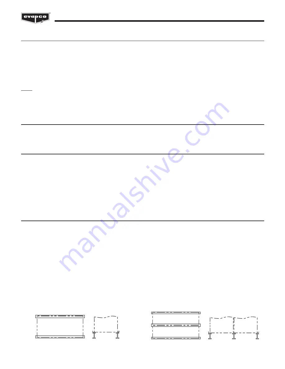
Structural Steel Support
3’, 4’, 8.5’, 10’ and 12’ Wide Models
Two structural “I” beams running the length of the unit are required for supporting the unit. These beams should be located
underneath the outer flanges of the unit. (See Figure 1.)
17’, 20’ and 24’ Wide Models
Three structural “I” beams running the length of the unit are required for supporting the unit. Locate two beams underneath the
outer flanges of the unit, and locate one beam longitudinally along the center of the unit. (See Figure 2.)
All Models
Mounting holes, 3/4” in diameter, are located in the bottom flange for bolting to the structural steel (see certified print for exact bolt
hole location). Bolt the bottom section to the steel support before rigging the top section.
Beams should be sized in accordance with accepted structural practices. Maximum deflection of the beam under the unit to be
1/360 of the unit length, not to exceed 1/2”. Deflection may be calculated by using 55% of the operating weight as a uniform load
on each beam (see certified print for operating weight).
The supporting “I” beams should be level before setting the unit. Do not level the unit by shimming between the bottom flange and
the beams as this will not provide proper longitudinal support.
Note: Consult IBC 2006 for required steel support layout and structural design.


