EVAPCO AT ATLAS Rigging And Assembly Instructions Download Page 19

AT ATLAS Induced Draft Counterflow Cooling Towers

19

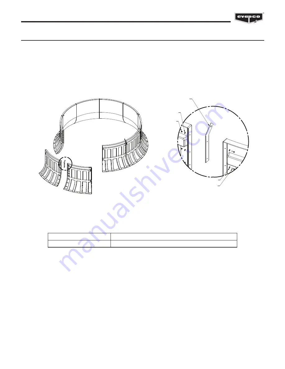
Figure 18 - Fan Cylinder Assembly

Fan Cylinder Assembly

The fan cylinder will ship in 10 sections for assembly and installation in the field. Each section will be joined with a flange as shown 

in Figure 18. Fan cylinder assembly should be performed on the ground with one person holding the sections up until the assembly 

is able to stand alone. See Table 9 below for hardware required to assemble the fan cylinder.
Lifting devices to be installed in between cylinder sections during assembly. Remove lifting device after installing fan cylinder if the 

tower has a Super Low Sound Fan.
Flanges should be cleaned prior to assembly. Each cylinder should have 5 lifting devices total, installed in every other cylinder 

panel seam.

ASSEMBLE CYLINDER PANELS USING

PROVIDED 3/8" HARDWARE

(SEE DETAIL A)

A

DETAIL A

(TYPICAL)

*ASSEMBLE CYLINDER PANELS

WITH LIFTING DEVICE SANDWICHED

BETWEEN EVERY OTHER PANEL

3/8" NYLOCK NUT

3/8" FENDER WASHER

3/8" FENDER WASHER

3/8" DIA X 1 3/4" BOLT

*REMOVE LIFTER AFTER INSTALLING CYLINDER

Units

Hardware Sizes

All ATLAS Units

3/8” (10mm) Nuts, Bolts & Washers

Table 9 - Hardware Sizes

Summary of Contents for AT ATLAS

Page 1: ...East DMCC Dubai United Arab Emirates 971 4 448 7242 p info evapco ae EVAPCO S A Pty Ltd A licensed manufacturer of EVAPCO Inc Isando 1600 Republic of South Africa 27 11 392 6630 p evapco evapco co za...

Page 2: ...ons to the Basin Sections 8 Assembly of Bottom Inlet Piping 10 Application of Sealer Tape to Casing Sections 11 Rigging Fan Sections 12 Assembly of the Fan Sections to the Casing Sections 13 Rigging F...

Page 3: ...rwise noted in the factory submittal all EVAPCO AT ATLAS towers ship in seven 7 sections per cell plus the drive system fan and fan cylinder Any special shipping configurations will be listed in the f...

Page 4: ...am under the unit to be 1 360th of the unit length not to exceed 1 2 13mm Deflection may be calculated by using 55 of the operating weight of the unit as a uniform load on each beam See certified prin...

Page 5: ...ded with horizontal drip channels and vertical splash guards to keep water from splashing out from between the cells The equalizer flume boxes are shipped loose for field assembly It is important to c...

Page 6: ...er tape to the mating flange of the drip channels see Figure 3a Fasten drip channels together end to end by driving a self tapping 5 16 8mm screw through the section end with the larger hole into the...

Page 7: ...ER OF SEALER TAPE CENTERED OVER THE MOUNTING HOLES END SIDE Application of Sealer Tape to Basin Sections Once the basin sections have been set on the support steel and all fasteners are installed the...

Page 8: ...bed Lower the casing section the rest of the way and fasten all four corners See Table 1 for recommended hardware Make use of drift pins to simplify the final positioning process see Drift Pin explana...

Page 9: ...ccessed from inside the unit Bolts can be driven upward through the mating flanges if access is restricted All rigging hardware is provided by EVAPCO Drift pins are by others The recommended drift pin...

Page 10: ...s are fastened securely in the unit s basin prior to shipment 2a Remove shipping strap under pipe 3 Align the riser pipe assembly with the upper pipe section in the bottom of the casing section Loosen...

Page 11: ...ave been rigged to the basin sections and all fasteners are installed the top flanges should be wiped down to remove any dirt or moisture Apply one layer of sealer tape centered over the mounting hole...

Page 12: ...t has 3 fan sections left right and middle On the middle section lifting ears are provided for lifting and final positioning For the left and right sections U bolts are provided The hook of the crane...

Page 13: ...e Drift pins should be used to align the fan section with the casing section The installer will need to attach the fan section end panels to the casing section end panels and the fan section side pane...

Page 14: ...ched to the inside of the casing and fan section panels as shown in Figure 12 Once the sections are mounted the flanges of the rigging channels must be bolted from inside the unit Use hardware noted i...

Page 15: ...itioning of the unit The preferred method for extended lifts is to use slings under the unit as shown in Figure 14 below Spreader bars should always be used between the cables at the top of the sectio...

Page 16: ...RR 375 400 in lbs 33 ft lb 45 Nm LRR 450 145 in lbs 12 ft lb 16 Nm LRA 485 240 in lbs 20 ft lb 27 Nm Floating Shaft Installation Alignment The fan motor and gear reducer will ship mounted to the mecha...

Page 17: ...allation Manual and Figure 15 H LOCKING COLLAR BUSHING FAN BLADE TOP OF GEAR BEARING GEAR SHAFT HUB Figure 15 Hudson Fan Mounting Table 7 Moore Fan Hub Distance Table 6 Hudson Fan Hub Distance Gear Dr...

Page 18: ...aligned and the fan assembled onto the gear output shaft the entire assembly should be lifted onto the fan section Figure 17 The hook of the crane must be a minimum of 17 above the lifting ears See T...

Page 19: ...ng devices to be installed in between cylinder sections during assembly Remove lifting device after installing fan cylinder if the tower has a Super Low Sound Fan Flanges should be cleaned prior to as...

Page 20: ...within the cylinder before attaching to fan section Measure the clearance between each fan tip and the cylinder with a tape measure making sure it is 7 8 22mm or less Fasten to fan deck using hardwar...

Page 21: ...applied between the fan cylinder and the fan sections as well as around the torque tube APPLY CAULK SEALANT AROUND GEAR MOTOR BASE TORQUE TUBE APPLY CAULK SEALANT BETWEEN FAN STACK AND FAN SECTIONS F...

Page 22: ...f your unit is accessorized with an external service platform assembly with a vertical ladder this equipment is shipped in the basin of your unit In some cases they are shipped separately due to other...

Page 23: ...PPORT TO DECK SUPPORT USING 5 8 15 9mm GRADE 5 HARDWARE FRONT TOEPLATE RAILING FITTING SECURE RAILING FITTING TO FRONT TOEPLATE USING 3 8 10mm GRADE 5 HARDWARE DIAGONAL SUPPORT CONNECTION PLATE SECURE...

Page 24: ...EVAPCO Inc P O Box 1300 Westminster MD 21158 USA Phone 410 756 2600 Fax 410 756 6450 E mail marketing evapco com 2020 EVAPCO Inc Printed on recycled paper using soy based ink...

Reviews: