


AT ATLAS Induced Draft Counterflow Cooling Towers
16
5. Check angular and axial misalignment between the drive shaft and both the motor and gear drive couplings.
6. Check angular misalignment with a dial indicator on gear drive side.
7. Attach the dial indicator support to the drive shaft and position the indicator tip to read off the opposite side flange.
8. With the dial indicator set to zero, rotate the shaft 360° and record the indicator readings at 90° increments.
9. The range between minimum and maximum values should be less than 0.010” (0.25mm). If alignment is out of tolerance, add
shims (not exceeding 1/4”).
10. When the angular alignment is within the acceptable ranges as mentioned in step 9, securely tighten all gear drive hardware.
11. Repeat steps 6 through 10 on the motor side of the drive shaft.
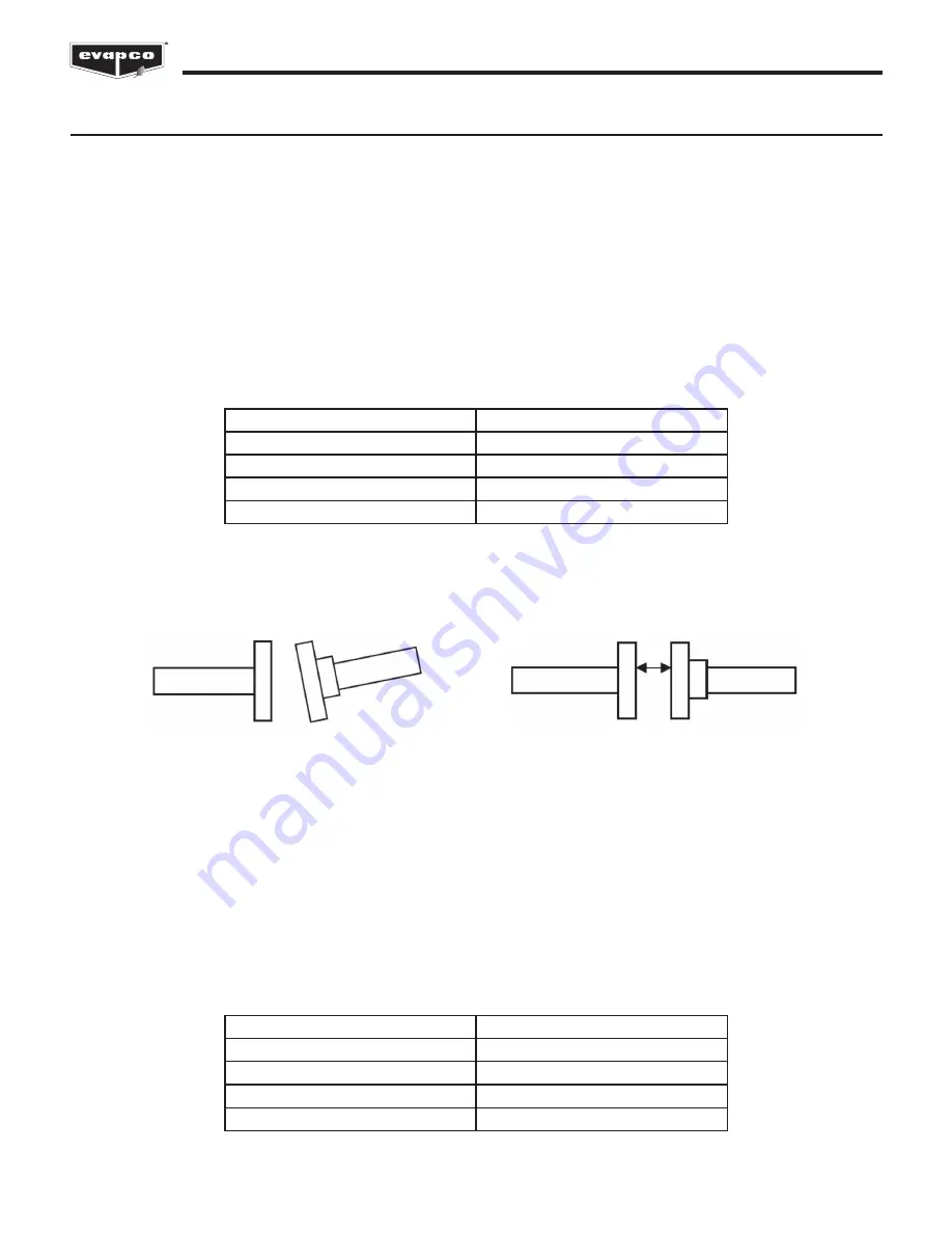
12. Check axial misalignment with a tape measure or dial caliper. Refer to Table 5 for axial alignment gap limits.
Angular Misalignment
Axial Misalignment
Table 4 - Torque Requirements for Floating Shaft Assemblies
Shaft Model
Torque Requirement
LRR 350
400 in-lbs (33 ft-lb 45 Nm)
LRR 375
400 in-lbs (33 ft-lb 45 Nm)
LRR 450
145 in-lbs (12 ft-lb 16 Nm)
LRA 485
240 in-lbs (20 ft-lb 27 Nm)
Floating Shaft Installation & Alignment
The fan motor and gear reducer will ship mounted to the mechanical equipment support. The system will be prealigned in the
factory, however alignment should be verified prior to rigging the mechanical equipment support to the fan section.
The steps for alignment of the floating shaft are:
1. Mount the drive shaft with the flexible element assembly on the gear drive input shaft using the supplied 3/8” (10mm)
hardware. All bolts, lock washers and nuts are supplied with the drive shaft kit.
2. Insert steel bushings into the composite flexible elements on the motor side.
3. Mount the drive shaft with the flexible element assembly on the motor output shaft using the supplied 3/8” (10mm) hardware.
All bolts, lock washers and nuts are supplied with the drive shaft kit.
4. Torque requirements for the bolts are listed in Table 4 (these values are dependent upon the shaft model). Use a torque
wrench to properly torque all drive shaft bolts.
Table 5 - Axial Alignment Gap Limits
Shaft Model
Axial Alignment Gap Limits
LRR 350
0.42-0.44 in. (10.7mm-11.2mm)
LRR 375
0.53-0.55 in. (13.5mm-14.0mm)
LRR 450
0.42-0.44 in. (10.7mm-11.2mm)
LRA 485
0.58-0.62 in. (14.9mm-15.9mm)


