background image

 THE COMPONENTS


[


21


]

the Filters section

It’s the upper side of the front panel. It’s the home of the three filterboards and related audio preamplifier and 

CV injection circuits and controls.

They are labeled as A, B and C.

Most of the features available are common for all three filters, with the exception of the A Filter Overload circuitry, 

shown in form of 

OVER/CLEAN

 switch, and the B-

STEREO

 mode.

The Circuit

The three filters are our personal elaboration of the Sallen-Key filter thought by Nyle Steiner in his 1974  

version of his famous design, hosted in the great Steiner-Parker Synthacon. It was a 12 dB/oct slope and it still 

remains a 12 dB/oct slope. But via the internal routing of VERTICE you can reach a slope of 36dB/oct nominal. 

In real-life however attenuation is less, max about 30 dB/oct, depending by input level, resonance control and 

Mode type. Electronically speaking: a diode network is used in place of the two variable resistors which make 

Sallen-Key filters useful for music. The obvious characteristic of a synthesis filter is the voltage-modulable 

Cutoff, so here is the magic: using a "side effect" of diode, their variable resistive behavior in front of a direct 

bias current, he made it. However diode generally are for other purposes, so this particular use can be source 

of "strange" behaviors.

Diode are common to reject current flow if the potential difference between anode and katode are less than, 

usually, 0,5-0,7V (silicon, small signal): if this difference is not reached they stay deactivated. So, since is exactly 

the audio signal which flow into the diode network it can activate, or not, a diode. It can be little up or little 

down than its threshold. This is why Steiner filter can show high instability especially when high Resonance 

values are involved. As we will see later indeed, Resonance is a signal feedback directly into the audio path, in 

this case directly into the diode network. 

You can see the original 1974 Steiner VCF circuit in the inside back cover of this manual. Values are effective 

(with these component values you can build a working 1974 Sallen-Key Steiner filter).

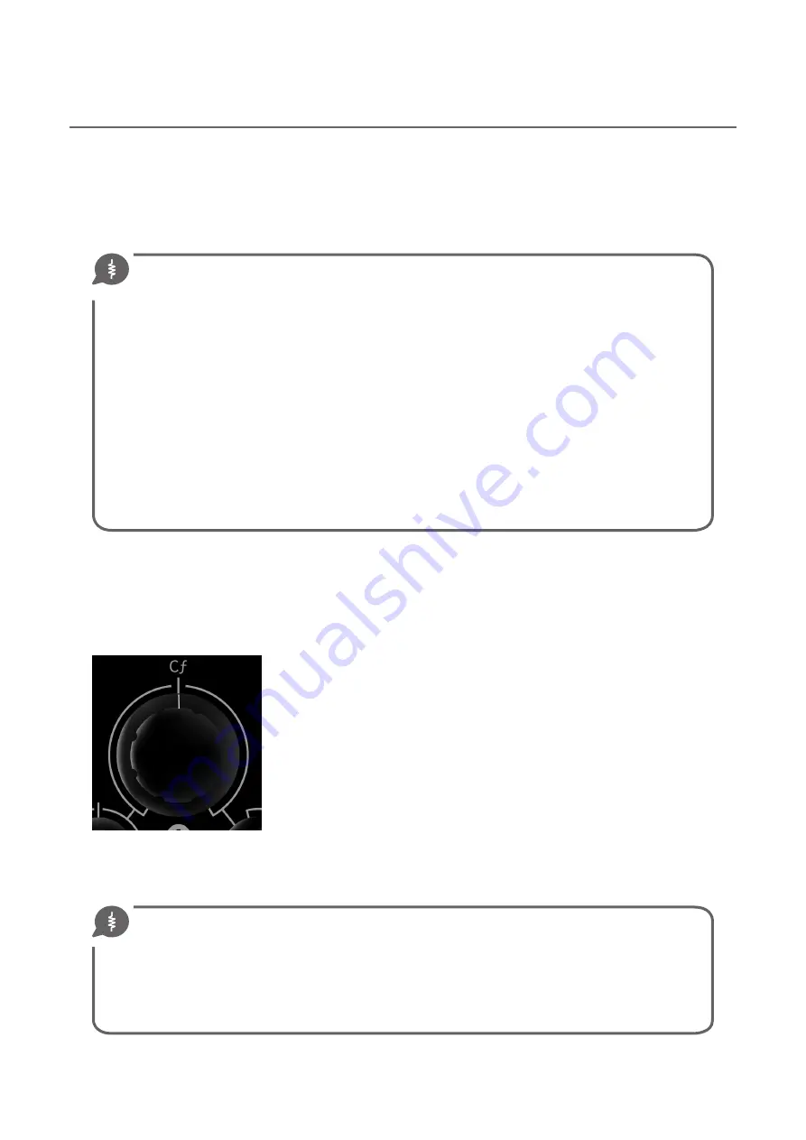
Cƒ means 

CUTOFF Frequency

. It is the point in the audible range where the 

filter start to run. It's the principal control of the singular filterboard. 

Its value is expressed in Hz and in the case of the VERTICE’s circuital design 

the excursion between maximum (fully counterclockwise) and minimum is 

about 

10≤Hz≥22000

., obviously biased by the MC

f

 position. We do not make 

any clear reference on the panel graphics about the Hz values because of the 

VERTICE’s strong 

musical

 character. If the intended use were measurements 

or other more precision purposes like mic amplifications, compressions and 

other meter-related applications it would be useful and reasonable to give 

them, but it's not the case. We want you to decide by your ears, not by your 

eyes. We follow this philosophy on every models/modules we design.

As said the control of 

MasterCƒ

, explained later (

page 37) exerts a strong influence in the behavior of the three 

individual Cƒ, so it is therefore useful to operate the four controls concurrently, although not necessarily at the 

same time. With five minutes of use you can easily understand the ratio between the four elements.

Where is my Cutoff Frequency?

To understand at what frequency you have placed your Cutoff simply you can increase the Emphasis 

value to obtain a signal peak around the Cutoff frequency. Conversely if you leave the Emphasis control 

close

 to zero you will notice instead the classic -3dB behavior. By mathematical definition in fact the Cutoff 

frequency is located in correspondence of this attenuation.

In real tough life instead, with a true zero Emphasis setting you don't really obtain a -3dB behavior from 

Vertice. The signal loss is a bit more giving a "10-11 dB/oct" slope. This happen because of a small potential 

leak due to the passive feedback method, so it's natural, almost vegan I should say...  :)

Summary of Contents for Vertice

Page 1: ...USER S MANUAL...

Page 2: ......

Page 3: ...al Rev 1 4 Copyright 2014 2018 Euterpe Synthesizer Laboratories All rights reserved Published by INDUSTRIE CREATIVE Turin Italy Written by Stefano Bersanetti Proofreading by Tom Charles Edwards ISBN 9...

Page 4: ...ctions 11 panel graphic overview 13 signal flow 15 THE COMPONENTS 17 the Connections Panel 17 the Filters section 21 the Masters section 37 the Envelope Generator section 41 the power module 48 USING...

Page 5: ...Dedicato a Walt Bruno e Lorenzina con immenso amore Stefano...

Page 6: ...o synth available today and at the same time another mono signal splitting it and take care of them all in a totally independent or completely related way Or three mono signals together summed distort...

Page 7: ...is at the beginning of the safety zone the orange zone on the panel and A input level is to max OR when Staccato Continuo is to max and A input level is to flat position Obvioulsly the external signal...

Page 8: ...e momentary switch on the panel act like a gate signal exactly like using the EG Gate input with a common Gate emitting keyboard Rear outputs are great to feedback them into front inputs For example y...

Page 9: ...g up quick overview Your first patch signal into A raise the A audio level let the signal flow into the B and the C filter in serial mode Use the Serial out or the Parallel in this case is the same to...

Page 10: ...VERTICE Filterbank section provides in depth description of some inside dynamics and various usage tips and tricks Please read this chapter to fully understand your VERTICE Analog Filterbank Some fun...

Page 11: ...the dedicated LED blink up saying Yeah bitch When you switch it ON you can eventually turn down STACCATO CONTINUO knob fully counterclockwise in STACCATO position This is the most silent way to switch...

Page 12: ...reasonable to think that a small change in tone with the same settings can be detected and if you like the analog philosophy this is the genuine product proof like as in orange juice that if it depos...

Page 13: ...ter A with distortion circuitry Filter B Filter C MASTER LEVEL with Staccato Continuo function Two Resonancepaths for each filter MASTER CUTOFF with dedicated CV level AUDIO and CV input LEVEL A to A...

Page 14: ...IO IN Allows you to feed audio into VERTICE A B and C filterboards INPUTS CV IN You can control the corresponding Cf with an external CV signal Master Cutoff INPUTS AM input let you control the dynami...

Page 15: ...mpacting and tough sounding possibilities PARALLEL Using the module it is possible to sum the A B or C outputs It is a noble possibility if you notice there are three independent audio inputs it means...

Page 16: ...Square input signal however can obviously produce smooth outputs CV thanks to the ADSR controls Contrabass tone routing tips the first simple patch to do This is a very basic configuration hosted in t...

Page 17: ...nuances of the two three four modalities are fully investigated For now treat them as your intuition suggests like i e Parallel sum of signals Serial sequence of signals Reference Labelling In additi...

Page 18: ...roximately the point of standard Moog 1V oct but your unit can be slightly setted differently because of the component tolerances in this passive old style regulation system Adjusting this setting is...

Page 19: ...these ports into your patch bay to obtain more comfort during patching E g you may want to create something like this Audio into B B into C C to output Then you can take the B signal and route it int...

Page 20: ...CF or the VCA via front panel switch So you can have your loop or your triggered ADSR response driving both MCf aka VCF and e g A filterboard A Cf CV input or both MCf and VCA via AM input or VCA AM i...

Page 21: ...ectly into the diode network You can see the original 1974 Steiner VCF circuit in the inside back cover of this manual Values are effective with these component values you can build a working 1974 Sal...

Page 22: ...r its oscillating nature an alternatedsignal AC frequencyofanACsignal notzeroHz andthisisenoughforthecapacitor thesignalpass through But likesomuchinphysics itisallatransientmatter Thismeansthatcapaci...

Page 23: ...allychangeasaconstructioncharacteristic This is not the right place to dwell around this argument just be content of the sequent little reasoning Using Pythagoras and vectors we can transform the prev...

Page 24: ...filter slopes making it more or less aggressive on the harmonic contents Generally speaking in Vertice MORE EMPHASIS MORE AGGRESSIVE SLOPES Alternative Emphasis way in order to tame the too much dyna...

Page 25: ...very inaccurate both in level and intonation and you can often notice a sensitive pitch unstability during the flowing of the minutes Mixing the three autooscillating VCF togheter can produce very int...

Page 26: ...ur filterbank is not a precision tool a bistoury It s more like a Viking battle axe We designed the alternative resonance way transistor specifically to cover the lack of stability that high resonance...

Page 27: ...nuances Low Emphasis levels are useful to create slow bassline and to correct too dark track without impacting too much on their harmonic structure Remember that low slope values are equal to less ph...

Page 28: ...and too much Emphasis As a general info valid for both Diode or Transistor position you can split the Emphasis pot race into two half to the left the safe zone to the right the ok let them understand...

Page 29: ...ll gradually notice that the behavior become very unstable with changes in both fast and slow rates with cyclic sometimes random ballet Arrows in the graph are indicating this behavior instability how...

Page 30: ...mances Instability of maximum level Emphasis Because of Steiner s classic resonance way diode strongly analogue nature these high Emphasis levels makes the Cutoff so unstable to generate a big slip fr...

Page 31: ...lters we think that a response too sharp often results too unnatural and unmusical compared to a softer although effective slope 18dB oct is not 24 but is also not zero And you can achieve a more aggr...

Page 32: ...o emphasize the high content of snares hi hat atmo pads and whatever need a full chlorine clarification In simple re amp modality HP can be useful if presence is the target sacrificing bass response H...

Page 33: ...mode circa 8 5Vrms In all the circumstances except for the well know very low Davoli s output level the behavior of the VERTICE s input stage is optimal and the range until full distortion is larger...

Page 34: ...ns that it discharge part of the injected energy to the main ground plane of Vertice This is a non professional non clean approach and I m here to underline it Why Well First because there is nothing...

Page 35: ...related two output ports The stereophonic signal is obviously processed by the two A and B filters linked via MASTER Cutoff control In this configuration PARALLEL becomes MONO and presumably the LEFT...

Page 36: ...y a simple active buffered circuit that make a true electric distortion caused by a current overload of two transistors We make them suffer Obviously the A preamplifier represents the input level for...

Page 37: ...gular 0 10V And just like the slaves it s attenuated by the related CV level potentiometer graphically connected on the panel But remember that the Master just controls the slaves so as a moment ago m...

Page 38: ...s noise floor is 77dB 2 in a 24bit digital scale It is not exceptional at all but it is quiet enough to meet the most case of applications Obviously turning down the input material or cut it totally o...

Page 39: ...t the same but with a little of I don t know USAGE NOTEs for the Vertice AM INPUT a delicate point in the circuitry AM input accepts standard 0 5V 0 5V 5V and standard audio voltage levels With this v...

Page 40: ...nt less final amplification coming from your VERTICE possibly in the case of live situations with some guitar pedals such digital delay or reverb and without a mixer between the audio chain In order t...

Page 41: ...from very slow to audio range modulations max circa 170Hz the VCF VCA selector to route the CV between the two main modules the anti vandal high end super professional Trigger button to have the pleas...

Page 42: ...meters slowly moving esoteric pads Release is a time control and thus is affected by the Percussive Smooth Slow switch position EG Level This pot can attenuate to zero the CV produced by the EG module...

Page 43: ...an activate the Loop function We say can because the effective loopingsituationishighlydependentontheADSRandRatesettings Allthefourparameters contribute to modify the looping rate and status so there...

Page 44: ...ly turn it right to smooth a bit the initial shape of the loop But Attack is another tricky part of this circuit and it often turns off your loop when in flat or more clockwise position due to the min...

Page 45: ...etting we suggest to start with turned into the looping modality It simply doesn t work There is not enough Release level to maintain looping and the max Sustain setting produces a straight note when...

Page 46: ...mely dynamic and sensitive to CV So for example avoid to doubling the EG signal to the VCA module via rear port panel switch It probably will be musically pointless and eventually dangerous for circui...

Page 47: ...play anymore and this is why you shout down the signal source VERTICE is not tired enough VERTICE want to play drops right now and you can t do anything about that bitch Well togivingtoourbelovedVERT...

Page 48: ...0mA 15V Voltage set accuracy 2 max Minimum load 10 of rated max current Ripple and noise 20MHz BW 1 of Vout mVpp Overload protection by current limit 105 min of Inom fold back automatic recovery Overv...

Page 49: ...w crazy We want it can be astonishing for a long time since you bought it not just a one night love There is plenty of more perfect more usable more inexpressive and money saving analog and digital fi...

Page 50: ...ntotheSumming Circuitry instead labeled by the Greek and mathematical symbol In this case this routing method can exclude the B filter and obviously also the C from this audio line But remember that a...

Page 51: ...eristic is required In other words VERTICE can be a reliable source of well mixed very boosted pure electric audio material So you can use it not only for filtering general mix needs are satisfied too...

Page 52: ...om the Parallel Output 3 obviously there are more complex combinations sons of the two previous especially using the rear ports and the CV inputs together Experiment with some different audio input ma...

Page 53: ...n see in the ROUTING chapter at page 15 the C filter virtually can t be available for any use But in the real life C is still functional and available for crazy Emphasis auto oscillations and to recei...

Page 54: ...is preeminently generated around the Cf frequency position and changing that position often generate a very musical half tone difference from the foundamental note besides changing the waveform So you...

Page 55: ...at tempo and you re just become a real pro FEEL THE DARKNESS Rear A into Front B Rear Ser into Front A A to Par B to Stereo Just raise up the A Emphasis level to obtain something like be inside Alien...

Page 56: ...ircuits It is not so dangerous but maybe also not so useful musically speaking We leave it there only as a side effect of a strongly wanted huge dynamic range with all the expressive and tonal possibi...

Page 57: ...TICE as a compressor you must 1 Procure yourself a stereo BD signal or obviously any other signal that may trigger the Eg 2 Use one cable to feed audio signal into audio path of VERTICE It can be A B...

Page 58: ...her force it to be so level grow It s a bit tricky but this is the only way you can use to obtain compression from VERTICE It can be a very silent compression and still remains strongly effective on a...

Page 59: ...n a pumping version of the Unnatural Position described earlier I mnotheretoexplaintoyoutheCompressiontheory givingitasacommonknowledge butabriefconsideration about Attack and Release matter can be do...

Page 60: ...rotected by level reduction simply bypassing Vertice Or simply move your triple saw square with rhythmical modulation and remain synchronized with the other machines of your set up And with all these...

Page 61: ...ponent failure we need to take direct care of the unit So we will give you all the necessary informations to return it to our laboratory Programmed Obsolescence Ifyounoticeaproblemandhavetheskillsandm...

Page 62: ...the job done than expiring instantly your warranty for nothing If you communicate your idea to us we take care to note down it and your warranty will remain active1 If not and something goes wrong we...

Page 63: ...As always taking a look inside your new machine can be a rich source of knowledge about it and about the rest of the world Please note the dimensions of our pcbs of our power supply and related anti E...

Page 64: ...er electronic device the VERTICE circuitry is very sensitive to water rain or other kind of liquid especially if they containdilutedsugarsorsalts IfsomesortofliquidisintouchwiththecircuitsTURNOFFTHEUN...

Page 65: ...nces with restrictions of use referred to in Article 4 paragraph 1 and values of maximum tolerated concentrations by weight in homogeneous materials VERTICE is CE compliant following the sequent EEC S...

Page 66: ...NOTES PATCH ID DATE AUDIO SOURCE CV SOURCE A FILTER B FILTER C FILTER MASTER CUTOFF EG GATE AM INPUT INPUT SETTINGS...

Page 67: ...Giovinetto Emanuele Prochietto Marco Trivellato Sergio Taglioni and all APM team Luigi Cominetti Paolo Groppioni GRP Synthesizers Danilo Bianchi Samuele Castucci Mauro Manzio Gerbaudo Elia Pellegrino...

Page 68: ...Ratio et Cogitatio Unicam Fidem Sunt...

Page 69: ......

Page 70: ......

Reviews: