background image

7100A User Manual

4-5

Control / Limits

Current limit by threshold. 

If  I

RMS

> I

max

:

firing angle variation.

V2 control in ‘Burst mode 16’

Current limit by threshold. 

If  I

RMS

> I

max

:

firing angle variation.
P control  in ‘Burst mode 16’

Power limit by 
control in ‘Burst mode 16’ 

taking P

max

into account  

Current limit by transfer.  

If  I

RMS

2

(%) > V

2

(%): 

automatic transfer to I

2

control by firing

angle variation. 

Current limit by transfer.  

If  I

RMS

2

(%) > V

2

(%): 

automatic transfer to I

2

control by firing

angle variation. 

Power limit by control (variation of
firing angle; new ratio between P and
setpoint.

I

Control

Firing

Control 

Potentiometer

Operation

mode

type

Name

Action

of limit

C16

V2CL

VICL

PA

V2CL

VICL

I

2

I lim

Thyristor unit 
current recalibration:
set threshold 

I

max

I lim

Thyristor unit 
current recalibration:
set threshold 

I

max

VI lim Recalibration of 

power control loop: 
set ratio between
P and setpoint

I lim

Thyristor unit 
current recalibration:
set ratio between
I (%)  and setpoint 

I lim

Thyristor unit 
current recalibration:
set ratio between
I (%)  and setpoint 

VI lim Recalibration of 

power control loop: 
set ratio between
P and setpoint

I lim

Thyristor unit 
current recalibration:
set ratio between
I (%)  and setpoint

Table 4-2 Operation of current and power limits

4.3. CURRENT AND POWER LIMIT SPECIFICATIONS

The table below summarises the operation of the limits used in the 7100A series power thyristor units. 

Reminder

: Recalibration sets the unit’s new nominal current rating (I

N

).

Summary of Contents for 7100A

Page 1: ...7100A User Manual Single Phase Power Thyristor Units Issue 4 4 HA176499ENG March 2011 ...

Page 2: ...right Eurotherm Automation 2002 All rights reserved All reproduction or transmission in any form whatsoever and using any procedure electronic or mechanical including photocopying and recording without written permission from Eurotherm is strictly prohibited Ref HA176499 ENG Issue 4 4 2011 03 ...

Page 3: ...power thyristor units 1 1 Chapter 2 Installation 2 1 Chapter 3 Firing modes 3 1 Chapter 4 Control and limits 4 1 Chapter 5 Alarms 5 1 Chapter 6 Maintenance 6 1 Eurotherm 7 1 PURPOSE OF MANUAL This is the Issue 4 4 User Manual It describes the Basic Version and all options for 7100A series power thyristor units with current ratings from 16A to 250A ...

Page 4: ...ELECTROMAGNETIC COMPATIBILITY EMC 7100A products installed and used in accordance with the user manual are designed for an industrial environment and must not be used in the home EMC TEST STANDARDS The units comply with the following EMC test standards in accordance with the AC semiconductor motor controllers and conductors for non motor loads standard EN 60947 4 3 Immunity EN 61000 4 2 EN 61000 4...

Page 5: ...conditions met Normal operation CHK SET push button Characteristics correspond to product code Chapter 1 Supply protection protective earth power control Chapter 2 If external supply for electronics or fan Page 2 12 Chapter 4 Pages 2 10 2 11 Chapter 3 Chapter 4 Page 5 7 Chapter 4 Page 5 7 Page 3 3 Alarms signalled Chapter 5 Page 5 5 5 6 I lim potentiometer Ilim VIlim potentiometers Control signal ...

Page 6: ...ical specifications 1 7 1 2 1 Power 1 7 1 2 2 Load 1 7 1 2 3 Dimensions 1 7 1 2 4 Control 1 8 1 2 5 Firing Modes 1 8 1 2 6 Control 1 8 1 2 7 Signalling 1 8 1 2 8 Alarms 1 9 1 2 8 1 Load Monitorin Alarms 1 9 1 2 8 2 OverLoad Alarms 1 9 1 2 8 3 Alarm Relay 1 9 1 2 9 Protection 1 10 1 2 10 Mounting 1 10 1 2 11 Environment 1 10 1 3 Coding 1 11 ...

Page 7: ...se with the open loop code OL or the transformer primary code XFMR The Power Control option VICL is not available on the lite version Full version units 100 A Power Control option VICL only or combined with other options Alarm option GRF or DLF combined with Control option V2CL I2 or VICL Overload option ICO Warning The Full Version is only available up to 100 A maximum Warning Selective trigger l...

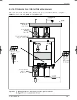
Page 8: ... voltage EUROTHERM ε 7100A 16 A 500 V PE A N A 3 1 0 V A 3 2 R I 3 3 5 V A A F 1 6 2 3 0 1 7 1 8 N ON HEAT Internal wiring diagram Power terminals load side Control terminal references User label Auxiliary supply terminal references if specified Electronics power supply Firing request Burst mode or single cycle Auxiliary supply terminal block if specified 2 T1 1 L1 3 L2 4 T2 1 1 1 7100A unit from ...

Page 9: ... thyristor unit 16A to 63A full version and 63 A lite version EUROTHERM ε 7100A 63A 500 V PE 3 L2 4 T2 2 T1 1 L1 A L R 7 1 1 a 7 2 1 b A N A 3 1 0 V A 3 2 R I 3 3 5 V A A F 1 6 2 3 0 1 7 1 8 N GRF DLF ON HEAT 1 1 2 7100A units from 16A to 63A full version and 63 A lite version ...

Page 10: ...IM Internal power wiring diagram Protective earth terminal Power terminals supply side Control terminal references V2CL or VICL options Current limit GRF option serious alarms Rating nominal current nominal voltage Power terminals load side User label Electronics power supply Firing request Phase Angle V2CL VICL and I2 options Current calibration DLF option Diagnostic alarm push button VICL option...

Page 11: ...ternal fuse for 125 to 250 A units Control Terminals Power Terminal Supply side Internal Fuse Compartment Protective Earth Terminal Not used Power Terminal Load Side Not used Fan 250 A only Fan Power Supply 250 A only Over Temperature Alarm 250 A only A N A 0VA RI 5V A 31 32 33 1 1 4 7100A units from 125A to 250A lite version only Figure 1 4 General view of 7100A power thyristor unit 125A to 250A ...

Page 12: ...tegories of use The categories of use applicable for each unit are indicated on the identification label AC 51 Non inductive or low inductance loads furnace resistances Resistive load with low temperature coefficient AC 55b Switching of incandescent lamps Short wave infrared elements SWIR units 100 A only AC 56a Switching of transformers Transformer primaries and high temperature coefficient resis...

Page 13: ... current squared I2 option in Phase angle Open loop in Phase angle Linearity and Stability Better than 2 of full scale Current limit Option depending on firing mode V2CL option Phase angle Automatic control transfer V2 I2 or V I I2 Current recalibration set by potentiometer on front panel Burst mode 16 cycle base Current limit with fixed threshold set by potentiometer on front panel Calibration A ...

Page 14: ...d Signalling Red T LED if one of the I2 VI or CL alarms or regulation options is selected Alarm relay contact with any one alarm 1 2 8 2 Overload alarms Option Overload alarm Cut out if current threshold exceeded ICO Option Only available for Burst Firing C16 or C64 with DLF option not available with Short wave infrared elements transformers and codes VICL and V2CL Two alarm thresholds instantaneo...

Page 15: ...n of the fuse is accessible on the MSF block Fuses of replacement see chapter 4 No fuse for Short wave infrared elements in Burst mode and Single cycle firing or Phase angle without Current limit 1 2 10 Mounting Mounting type Attachment plate fixed to unit on symmetrical EN50022 DIN rail or bulkhead mounting for ratings 125 A bulkhead mounting only 1 2 11 Environment Use 0 to 45 C at nominal curre...

Page 16: ...French FRA English ENG German GER 4 Fan power supply Code 200A No fan XXXX 250A 115 V fan and 115 V 115V 230 V fan and 230 V 230V 10 Selected options Code Base version No options Standard V2 control End of code NONE Version with options Selection of options YES Basic selection 6 Firing mode Code Phase angle PA Advanced single cycle 1 base cycle non firing by half cycles ASC Burst mode Single cycle...

Page 17: ...type Code With DLF option Short wave infrared SWIR Low temperature coefficient load LTCL Without DLF option or High temperature coefficient load XXXX 13 Load Monitoring alarms Code Serious Alarms Thyristor short circuit Total Load failure over temperature for rating 250 A GRF Partial load failure and Serious alarms DLF No alarms NONE 16 Alarm relay contact Code With alarm option Contact closed on ...

Page 18: ...ails mounting 2 5 2 2 4 2 Bulkhead mounting 2 5 2 2 5 125 A to 250 A units mounting 2 6 2 3 Wiring 2 7 2 3 1 Power connections 2 7 2 3 1 1 7100 A units from 16 A to 100 A wiring diagram 2 8 2 3 1 2 7100 A units from 125 A to 250 A wiring diagram 2 9 2 3 2 Control connections 2 10 2 3 2 1 Control terminal block 2 10 2 3 2 2 Control signal 2 11 2 3 2 3 Power supply for electronics 2 12 2 3 2 4 Alarm...

Page 19: ...al currents correspond to use at ambient temperatures of no more than 45 C Overheating may cause incorrect operation and may even lead to components being damaged Danger It is the user s responsibility to wire and protect the facility according to best practice and applicable standards A suitable device ensuring that the unit can be electrically isolated from the supply must be installed upline to...

Page 20: ...ttachment plate Screws 16 A to 63 A One vertical One EN50022 One vertical 2 x M4 plate symmetric rail plate 80 A and 100 A Two horizontal Two EN50022 Two horizontal 4 x M4 plates symmetric rail plates 125 A Not applicable Two horizontal 4 x M6 plates 2 2 2 MOUNTING DETACHING UNITS IN DIN RAILS fix one symmetric DIN rail rating 16 A to 63 A or two rails rating 80 A and 100 A in accordance with the ...

Page 21: ... 156 0 5 164 For M4 screw For M4 screw Figure 2 1 Attaching the 7100A power thyristor unit to a DIN rail 16A to 63A rear view Attachment hooks Mobile attachment hooks EN50022 DIN rail Catch to move mobile hooks downwards Attachment plate 164 82 2 2 3 16A TO 63A UNITS MOUNTING 2 2 3 1 DIN RAIL MOUNTING 2 2 3 2 BULKHEAD MOUNTING ...

Page 22: ...te Attachment hooks Figure 2 3 Attaching the 7100A power thyristor unit to DIN rails 80A and 100A rear view Lower attachment plate 210 0 5 Upper attachment plate For 2 M4 screws 226 80 0 5 For 2 M4 screws Figure 2 4 Bulkhead mounting using an attachment plate 80A and 100A rear view 2 2 4 80A TO 100A UNITS MOUNTING 2 2 4 1 DIN RAIL MOUNTING 2 2 4 2 BULKHEAD MOUNTING ...

Page 23: ...l 2 6 144 423 305 without fan 354 7 with fan 250 A units 124 For2 M6 screws For2 M6 screws 275 without fan 324 7 with fan 250 A units 2 2 5 125A TO 250A UNITS MOUNTING BULKHEAD MOUNTING Figure 2 5 125A to 250A 7100 A unit mounting ...

Page 24: ...or this range of standard current ratings is shown in figure 2 6 The protective earth terminal PE marked with the earth symbol must be wired to the protective earth see section Safety during installation The 7100A units 100 A are equiped of One thyristor controlled channel The protective earth terminal PE marked with the earth symbol must be wired to the protective earth see section Safety during ...

Page 25: ...g 100 A no options self powered electronics Ph N Ph2 Load Supply protection and cut out installed by user Thyristor protection fuse Protective earth connection Internal power wiring diagram Control terminal references Controlled channel terminal supply side Direct channel terminal supply side Protective earth terminal Signal input terminal block Controlled channel terminal load side Direct channel...

Page 26: ... 500 V ON HEAT EN 60947 4 3 1 L1 2 T1 A N A 0VA RI 5VA 31 32 33 F A N 230 N 16 17 18 E X T N 21 22 L1 2 T1 1 L1 M S F 3a 3b 75 76 PE Load L2 N EXT block terminal Connection L2 or N E X T N 21 22 Fuse 1 A Fuse 1 A 2 3 1 2 7100A units from 125A to 250A wiring diagram The power connection to 7100A units is between one phase and neutral or between two phases depending on the nominal voltage for the th...

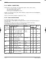
Page 27: ...mbers are marked on the front panel for available terminal blocks The table below gives details of all terminals and terminal blocks Terminal Terminal description Version Terminal Torque block name No Name Purpose capacity mm2 AWG Nm ANA 31 0VA 0 V for analogue signals Base or 32 RI for analogue signals Options 1 5 16 0 5 33 5VA Internal analogue 5V supply A F 16 230 230 V aux fan supply except SE...

Page 28: ... 0 V A 3 2 R I 3 3 5 V A Control signal connector 10 k potentiometer For input code 0V5 only 0 V 0 100 Internal 5 V analogue signals 0 V Analogue control signal a b A N A 3 1 0 V A 3 2 R I 3 3 5 V A ON HEAT ON HEAT 2 3 2 2 Control signal ANA Terminal The analogue control signal terminal block is labelled ANA The input available corresponds to the input type selected in the product code voltage or ...

Page 29: ...ure alarms may be acknowledged with a 5 V signal by connecting a contact between terminal 63 5VD internal and an ACK logic input terminal 62 available on the DIG IN terminal block An external 5 V supply may be used for this acknowledgement see figure 2 10 Note The DLF alarm can also be reset with the CHK SET push button 2 3 2 6 Connecting the reference neutral voltage EXT Terminal For any units fr...

Page 30: ...l and firing mode signalling 3 2 3 2 Burst mode codes C16 and C64 3 2 Firing delay XFMR option 3 3 3 3 Single cycle code FC1 3 4 3 4 Advanced single cycle code ASC 3 4 3 5 Phase angle code PA 3 5 3 6 Safety ramp 3 6 3 6 1 Ramp on start up 3 6 3 6 2 Magnetisation ramp XFMR option 3 6 ...

Page 31: ...alling Power supply for electronics Power supply fault flashing No reference Neutral flashing Thyristor firing request in Burst mode Single cycle and Advanced single cycle modes Reminder Advanced single cycle is only available with 4S and 6D three phase load configuration Thyristor firing request in Phase angle mode Table 3 1 Firing modes and base LEDs on front panel 3 2 BURST MODE codes C16 and C...

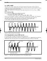
Page 32: ...tion In Burst mode firing with pure resistive loads the thyristors are fired at zero voltage crossing to avoid sharp current rises For an inductive load e g transformer primary switching the thyristors at zero crossing generates transient over currents see figure 3 2a This transient could cause the high speed thyristor protection fuse to blow in certain cases To avoid the over current the first th...

Page 33: ... whole number of half cycles for non firing and Important Advanced single cycle firing mode is only available for 4S or 6D three phase load configuration For duty ratios η η 50 the thyristor firing time is set to one cycle non firing occurs for half cycles For duty ratios η η 50 the non firing time is set to half a cycle firing occurs for whole cycles By using half cycles for non firing time the m...

Page 34: ...In Phase angle mode the power delivered to the load is controlled by firing the transistors over a part of each supply half cycle Control involves varying the thyristor firing angle θ It varies with the setpoint signal The load voltage vl and current il depend on the three phase load configuration Figure 3 5 Voltage and current in Phase angle mode a resistive load b inductive load ...

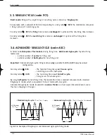
Page 35: ...t firing after the thyristor unit is powered up and after the firing is cut for more than 5 seconds The initial firing angle is approx 6 After the ramp the firing angle corresponds to the setpoint in Phase angle mode in Burst mode the thyristors fire fully once the ramp is complete t Current voltage Supply voltage Initial firing angle Figure 3 6 Start up ramp resistive loads t Load Voltage Supply ...

Page 36: ...l 4 2 4 1 1 Control parameters 4 2 4 1 2 Input Output ratio 4 2 4 2 Limitation adjustment options 4 3 4 2 1 Current recalibration options without power control 4 4 Settings 4 4 Settings with ICO option 4 4 4 2 3 Current and power limitation 4 5 4 3 Current and power specifications options 4 5 ...

Page 37: ...Loop OL The parameters are defined and explained in the table below Control Definition Code V2 Compensation of supply voltage variations V2CL Compensation of supply voltage variations with current limit VICL Power control with current and power limits I2 Current squarred control Only available with Phase Angle Mode code PA OL Open loop no control The output is the image of the setpoint Only availa...

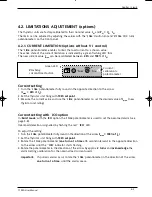
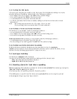
Page 38: ...e I lim potentiometer to set the desired value of Imax new thyristor unit rating Current setting with ICO option In Burst mode with the ICO option the I lim potentiometer is used to set the over load alarm see page 5 8 Over load detection is signalled by flashing the red ICO LED To adjust the setting 1 Turn the I lim potentiometer fully round in the direction of the arrow Imax 100 of IN 2 Set the ...

Page 39: ...een terminals HRC 67 and 0VC 66 represents The image of the maximum current VI lim potentiometer fully turned in the direction of the arrow The image of the maximum recalibrated power 1 V corresponds to 100 PN The control signal is equal to 1 V if calibrations are nominal Imax IN and Pmax PN The minimum value of the signal is 0 1 V Imax 20 and VI lim set to 50 of VN Imax Setting 1 Turn the VI lim ...

Page 40: ...pe Name Action of limit C16 V2CL VICL PA V2CL VICL I2 I lim Thyristor unit current recalibration set threshold Imax I lim Thyristor unit current recalibration set threshold Imax VI lim Recalibration of power control loop set ratio between P and setpoint I lim Thyristor unit current recalibration set ratio between I and setpoint I lim Thyristor unit current recalibration set ratio between I and set...

Page 41: ...Control Limits 7100A User Manual 4 6 ...

Page 42: ...toring 5 4 5 3 1 Setting the DLF alarm 5 5 5 3 2 PLF or TLF detection 5 5 5 3 3 PLF detection sensitivity 5 5 5 4 Load type matching 5 5 5 5 Disabling alarms for load failure signalling 5 5 5 6 Functions of DLF alarm push button 5 6 5 6 1 Setting Request 5 6 5 6 2 Diagnostic 5 6 5 6 3 Disabling 5 6 5 7 Over Load Alarm 5 7 5 7 1 Availability 5 7 5 7 2 Alarm conditions 5 7 5 7 3 Alarm Actions Memori...

Page 43: ...ero crossing Over temperature Firing inhibited Thyristor short circuit or Total load failure Partial load failure Red Red Orange Green Green OPTIONS Alarm options GRF DLF Total load failure Thyristor short circuit DIAGNOSTIC A ICO 250 A All versions ICO Over current Firing inhibited see page 5 7 HEAT Green Or Figure 5 1 Diagnosing operation and alarms according to front panel LED status ...

Page 44: ... exceeding a current threshold In addition the unit has active securities Network voltage default detection no network or supply voltage not high enough and frequency error Over temperature protection fan cooled units 250 A only 5 2 1 Firing cut off Over Load Overheating for current ratings 250 A only Supply voltage stops the thyristor firing 5 2 2 Alarm priority Only one alarm is signalled if sev...

Page 45: ...panel LEDs with GRF and or DLF option LED State Firing Typical Fault T GRF DLF HEAT stopped reaction red red orange green time Partial Load Failure OFF OFF Flashing PLF ON No 5 s to 13 s Total Load Failure OFF ON Flashing or TLF Flashing Thyristor Short Circuit OFF ON OFF THSC Over temperature T ON OFF OFF OFF Yes Table 5 1 LEDs for serious alarms or faults with GRF and or DLF options Two diagnost...

Page 46: ... current Total Load Failure TLF monitoring is only possible under the following conditions no over temperature or thyristor short circuit faults the rms voltage across load is greater than 40 of the nominal voltage 5 3 3 Partial Load Failure Detection Sensitivity Partial Load Failure Detection Sensitivity can be expressed in terms of a maximum number of load elements connected in parallel for whic...

Page 47: ...s below sets and diagnoses the status of the PLF detection circuit CHK SET Press until DLF LED flashes 4 5 s 0 t DLF DLF Setting performed Setting not performed Push button LED LED Figure 5 3a PLF detection setting request CHK SET DLF 3 s DLF 0 t Diagnostic disabled DLF Diagnostic active PLF fault Alarm on Alarm on Push button LED LED LED Alarm relay Alarm off Press until DLF LED lit Figure 5 3b P...

Page 48: ... the thyristor unit 5 7 3 Alarm Actions Memorisation Acknowledgement If an over current alarm is triggered thyristor firing stops at the end of the half cycle when the instantaneous current threshold is exceeded after approx 5 s of continuously exceeding the rms current threshold Over current alarm cut off is signalled as follows the position of the Alarm relay contact changes the ICO LED flashes ...

Page 49: ...Alarms 7100A User Manual 5 8 ...

Page 50: ...7100A User Manual 6 1 Maintenance Chapter 6 MAINTENANCE Contents Page 6 1 Safety during maintenance 6 2 6 2 Maintenance 6 2 6 3 Thyristor protection fuses 6 3 ...

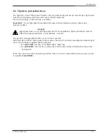
Page 51: ...rnal parts The heatsink temperature may exceed 100 C The heatsink remains hot for approx 15 minutes after the unit is shut down Avoid touching the heatsink even briefly while the unit is operating 6 2 MAINTENANCE Every six months check that the power and protective earth cables are correctly tightened see Wiring section page 2 7 If the load parameters change the operation of the PLF detection must...

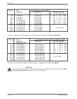
Page 52: ...o not provide protection for the installation Upline protection must be fitted non high speed fuses circuit breakers cut outs The product code specifies whether or not a fuse is present With the FUSE or MSFU micro switch fuse codes a fuse and fuse holder assembly corresponding to the current rating is supplied with the product for code FUSE the fuse is not fitted with a striker bar for code MSFU t...

Page 53: ...ns mm with striker bar H x W x D 16A CS176513U032 MSFU1451 16A 107 x 26 5 x 76 5 25A CS176513U032 MSFU1451 25A 107 x 26 5 x 76 5 40A CS176513U050 MSFU1451 40A 107 x 26 5 x 76 5 63A CS176461U080 MSFU2258 63A 126 5 x 35 x 76 5 80A CS176461U100 MSFU2258 80A 126 5 x 35 x 76 5 100A CS173246U125 MSFU2760 100A 146 x 40 x 94 125A CS176762U160 MSFU7100 125A 160A CS176762U315 MSFU7100 160A 200A CS176762U315...

Page 54: ...with Programming facilities Programmable Multi loop Process Controllers Solid State Contactors Power Controllers Paper and Paperless Data Recorders Data Acquisition and Management Instrumentation Supervisory Systems SCADA Process Automation Systems Eurotherm Limited is part of the Production Management Division of Invensys plc one of the world s leading automation and controls companies Eurotherm ...

Page 55: ...rotherm ie invensys com ITALY Como Eurotherm S r l T 39 031 975111 F 39 031 977512 E info eurotherm it invensys com KOREA Seoul Eurotherm Korea Limited T 82 31 2738507 F 82 31 2738508 E info eurotherm kr invensys com NETHERLANDS Alphen a d Rijn Eurotherm B V T 31 172 411752 F 31 172 417260 E info eurotherm nl invensys com NORWAY Oslo Eurotherm A S T 47 67 592170 F 47 67 118301 E info eurotherm no ...

Reviews: