


Installation
7100A User Manual
2-8
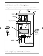
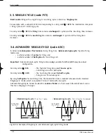
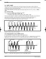
2.3.1.1. 7100A units from 16A to 100A wiring diagram
The power connection to 7100A units is between one phase and neutral or between two phases
depending on the nominal voltage for the thyristor unit.
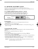
Figure 2-6 7100A power thyristor unit power and input signal connections
(rating
≤
100 A, no options, self-powered electronics)
Ph
N / Ph2
Load
Supply protection and
cut-out, installed by user
Thyristor protection
fuse
Protective earth
connection
Internal power wiring
diagram
Control terminal
references
Controlled channel
terminal
(supply side)
Direct channel
terminal
(supply side)
Protective earth
terminal
Signal input
terminal block
Controlled channel
terminal
(load side)
Direct channel
terminal
(load side)
ON
HEAT
ANA
31 0
VA
32
R
I
33 5
VA
7100
A
100 A / 230 V
EUROTHERM
PE
2/T1
1/L1
ε
4/T2
3/L2
71A2_Installation_ENG_Iss3.qxp 1/09/06 16:14 Page 2-8


