background image

SOSTITUZIONE DELLA POMPA A GAS CDS 302

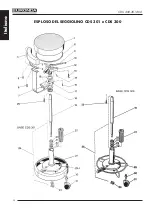
(disegno di riferimento esploso pag. 12)

1) Posizionare il seggiolino alla sua altezza minima.
2) Con una chiave esagonale da 4 mm togliere le tre viti (13) e rimuovere il cuscino
3) Togliere il seeger (24) e sfilare la parte superiore del seggiolino
4) Con una chiave esagonale da 5 mm togliere le tre viti (32) fissate sotto la piastra premipi-

stone (9) e sfilare la flangia (28) completa dei tre perni (15)

5) Impugnare saldamente con una mano la pompa a gas e con l’altra, con l’aiuto di un mar-

tello in plastica, battere sulle cinque razze della base (29) fino a che la pompa esce.

6) Infilare la nuova pompa a gas nella base, capovolgerla e battere sulle razze fino a quan-

do la pompa non si incastra perfettamente.

SOSTITUZIONE DELLA POMPA A GAS CDS 300/301

(disegno di riferimento esploso pag.14)

1) Posizionare il seggiolino nella sua altezza minima e capovolgerlo
2) Togliere il seeger (24) e sfilare la base (29) o (29A)
3) Con una chiave esagonale da 4 mm togliere le tre viti (13) e rimuovere il cuscino
4) Impugnare saldamente con una mano la pompa a gas e con l’altra utilizzando un martello

in ferro, battere sulle tre razze del mozzo fisso (12) fino a che la pompa a gas (19) non si
sfila

N.B. Attenzione a non battere sui tre grani (15)

5) Infilare nel mozzo fisso (12) la nuova pompa a gas, impugnare la pompa dopo averla

capovolta (il mozzo fisso sarà rivolto verso l’alto) e battere con un martello in ferro sul
mozzo fino a quando lo stesso non si incastrerà bene con la pompa

6) Verificare che le tre leve comando pistone (9) non si muovano rispetto al mozzo, eventual-

mente per togliere il poco gioco si può agire sui tre grani (15) usando una chiave esago-
nale da 2 mm.

7) Rimontare il tutto seguendo la procedura inversa a quanto sopra descritto 

CDS 300-301-302

11

Italiano

Summary of Contents for CDS 300

Page 1: ...ZIONE E MANUTENZIONE INSTRUCTION MANUAL AND MAINTENANCE EURONDA S p A Via dell Artigianato 7 36030 Montecchio Precalcino VI Tel 0445 329811 Fax 0445 865246 www euronda com info euronda com Certified c...

Page 2: ...nuale in qualsiasi forma senza l esplicito permesso scritto della EURONDA S p A Il contenuto di questo manuale pu essere modificato senza preavviso Pubblicato da EURONDA S p A Via dell Artigianato 7 3...

Page 3: ...ecessario che questo manuale venga letto attentamente prima del suo utiliz zo Infatti le nostre apparecchiature rispondono alle norme generali vigenti relative alla sicurezza e non presentano pericolo...

Page 4: ...I PER L USO P 9 PARTE 5 MANUTENZIONE ORDINARIA P 10 MANUTENZIONE STRAORDINARIA P 10 SOSTITUZIONE DELLE RUOTE CDS 300 301 302 P 10 SOSTITUZIONE DEL CUSCINO CDS 300 301 302 P 10 SOSTITUZIONE DELLO SCHIE...

Page 5: ...taggio l utilizzo la continua e regolare manutenzione L apparecchio deve essere usato in ottemperanza alle procedure contenute nel manuale e mai per scopi diversi da quelli in esso previsti L utente r...

Page 6: ...arlo a EURONDA S p A La garanzia ha inizio dalla data di consegna dell apparecchio al cliente comprovata dalla restituzione del tagliando di garanzia debitamente compilato e firmato In caso di contest...

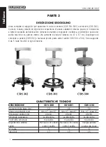
Page 7: ...L SEGGIOLINO E DELL IMBALLO DESCRIZIONE CDS 300 CDS301 CDS 302 Diametro della base cm 50 46 50 Altezza regolabile cm min 47 max 67 min 47 max 67 min 47 max 67 Ingombro imballo cm 52x52x55 52x52x55 52x...

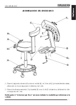
Page 8: ...ienale contenente 1 chiave esagonale 5 mm 1 chiave esagonale da 6 mm e 2 viti TSPCE M8 X 18 Prima di procedere al montaggio del seggiolino operare come segue 1 Aprire il sacchetto in polietilene D ed...

Page 9: ...ntemente svitate utilizzando la chiave esagonale in dotazione da 6 mm 2 Fissare lo schienale anatomico C alla staffa E con le 2 viti F in dotazione utilizzando la chia ve esagonale da 5 mm Nella parte...

Page 10: ...comando a pedale CDS 302 o manuale anello posto sotto il sedile CDS 300 e 301 Sono supporta ti da 5 ruote movibili in ogni direzione CARATTERISTICHE TECNICHE DESCRIZIONE CDS 300 CDS301 CDS 302 Diamet...

Page 11: ...ondit G1 del supporto schienale B si ottiene allentando le tre viti G utilizzando la chiave esagonale da 6 mm e facendo scorrere il supporto B lungo i fori ad asola fino alla profondit desiderata Fiss...

Page 12: ...tare il perno 30 e avvitare quello nuovo 4 Inserire la ruota nuova 31 nel perno spingendo con forza o battendo con un martello di gomma SOSTITUZIONE DEL CUSCINO CDS 300 301 302 disegni di riferimento...

Page 13: ...riferimento esploso pag 14 1 Posizionare il seggiolino nella sua altezza minima e capovolgerlo 2 Togliere il seeger 24 e sfilare la base 29 o 29A 3 Con una chiave esagonale da 4 mm togliere le tre vi...

Page 14: ...PARTE 6 ESPLOSO DEL SEGGIOLINO CDS 302 12 CDS 300 301 302 Italiano...

Page 15: ...43 12 2 Piastra sedile 200x200x5 vern 918055 13 3 Viti TSPCE M6 X 18 990208 14 1 Distanziale in nylon diam 60x35x10 918052 15 3 Perni diam 8 x 110 zinc 918047 16 1 Spessore in nylon diam 80x36 5x1 918...

Page 16: ...ESPLOSO DEL SEGGIOLINO CDS 301 e CDS 300 14 CDS 300 301 302 Italiano...

Page 17: ...1 Coperchio pistone 918006 12 1 Mozzo fisso 918001 13 3 Viti TSPCE M6 X 18 990208 14 3 Spina elastica diam 5 x16 984159 15 3 Grano P P M4x8 951073 16 2 Distanziale in nylon diam 70x46x1 918005 17 1 M...

Page 18: ...erie pla stiche Quando l apparecchio demolito non vi sono particolari istruzioni da eseguire Non abbandonare l apparecchio in luoghi non custoditi affidare la rottamazione ad imprese di smaltimento Pe...

Page 19: ...r equipment is designed in compliance with all current safety standards and do not constitute a hazard for the user provid ed that all instructions in the manual are observed Note also that reproducti...

Page 20: ...RT 4 INSTRUCTIONS FOR USE P 9 PART 5 ROUTINE MAINTENANCE P 10 SPECIAL MAINTENANCE P 10 CDS 300 301 302 WHEELS REPLACEMENT P 10 CDS 300 301 302 CUSHION REPLACEMENT P 10 CDS 300 301 302 BACKREST REPLACE...

Page 21: ...rations is strictly forbidden GENERAL INSTRUCTIONS The present manual has been drawn up to provide instructions regarding correct assembly operation routine maintenance The equipment must be used in c...

Page 22: ...it to EURONDA S p A The guarantee is effective from the delivery date of the unit to the customer which is confirmed by the return of the guarantee slip correctly filled in and signed In the case of...

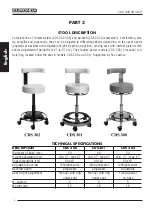
Page 23: ...CHINE AND OF THE PACKAGE DESCRIPTION CDS 300 CDS301 CDS 302 Diameter of base cm 50 46 50 Height adjustable cm min 47 max 67 min 47 max 67 min 47 max 67 Overall dimensions cm 52x52x55 52x52x55 52x52x55...

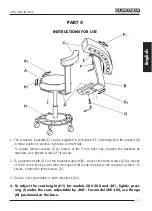
Page 24: ...bag D fixed to backrest support and containing one 5 mm Allen key one 6 mm Allen key and two TSPCE socket screws MA 8x18 Prior to assembly proceed as follows 1 Open the polyethylene bag D and remove...

Page 25: ...previously loosened screws G using the 6 mm Allen key supplied 2 Fix the anatomic backrest C to bracket E by means of the two provided screws F using the 5 mm Allen key The part 4 Instructions for us...

Page 26: ...ntrols CDS 302 or manual con trols ring located under the seat in models CDS 300 and 301 Supported by five castors TECHNICAL SPECIFICATIONS DESCRIPTION CDS 300 CDS301 CDS 302 Diameter of base cm 50 46...

Page 27: ...n screws F to secure 2 To adjust the depth G1 of the backrest support B slacken the three screws G by means of the 6 mm Allen key and slide the support B along the slots to the required position To se...

Page 28: ...shing it hard into the seat or tapping it in with a rub ber mallet CDS 300 301 302 CUSHION REPLACEMENT reference exploded drawings pages 12 and 14 1 Turn over the seat 2 Use a 4 mm Allen key to remove...

Page 29: ...erence exploded drawing page 14 1 Position seat at its lowest height and turn it over 2 Remove snap ring 24 and extract the base 29A or 29B 3 Use a 4 mm Allen key to extract the three screws 13 and re...

Page 30: ...PART 6 EXPLODED DRAWING OF STOOL CDS 302 12 CDS 300 301 302 English...

Page 31: ...x200x5 918055 13 3 Screws TSPCE M6 X 18 990208 14 1 Nylon spacer diam 60x35x10 918052 15 3 Zinc plated pins diam 8 x 110 918047 16 1 Nylon spacer diam 80x36 5x1 918059 17 1 Painted moving hub 80x8x185...

Page 32: ...EXPLODED DRAWINGS CDS 301 AND CDS 300 14 CDS 300 301 302 English...

Page 33: ...918006 12 1 Fixed hub 918001 13 3 Screws TSPCE M6 X 18 990208 14 3 Spring cotter diam 5 x16 984159 15 3 Dowel P P M4x8 951073 16 2 Nylon spacer diam 70x46x1 918005 17 1 Moving hub with nylon bushing 9...

Page 34: ...erials and plastic materials No particular precautions are required when demolishing the unit Do not dump the unit in an unguarded place consign it to a waste disposal agency for scrap ping Always ref...

Page 35: ...CDS 300 301 302...
Page 36: ...ZIONE E MANUTENZIONE INSTRUCTION MANUAL AND MAINTENANCE EURONDA S p A Via dell Artigianato 7 36030 Montecchio Precalcino VI Tel 0445 329811 Fax 0445 865246 www euronda com info euronda com Certified c...

Reviews: