


www.eurolube.com
EUROLUBE EQUIPMENT AB
–
PART NO 26700, 257-51, 257-52 / ART.NR. 26700, 257-51, 257-52
POWER RAM PUMP HOIST
4
www.eurolube.com
4
842 806 R. 09/12
Samoa Industrial, S.A. · Box 103 Alto Pumarín · 33211 Gijón - Asturias Spain · Tel.: +34 985 381 488 · Fax.: + 34 985 384 163
2012_09_26-10:30
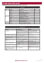
Operation
To raise the inductor for the first time:
1. Ensure there is nothing above the hoist. In addition, read the
WARNINGS AND PRECAUTIONS on page 2.
2. Move the control cabinet lever to the “UP” position. Do not
touch any part of the unit while it is moving!
3. Lift the inductor plate higher than the top of the drum. Stop
the hoist ascending further by moving the control cabinet
lever to the “NEUTRAL” position (centre).
To raise the inductor, (normal operation):
1. Before raising the inductor, the pump control valve must be
in the “OFF” position.
2. With new gaskets the pressure indicated on the “Ram
Control” dial must be 6-7 bar (with softer used gaskets the
pressure may be lower, to reduce slight fluid leakage). To
adjust the inductor air pressure, partially remove the “Ram
Control” regulator control so it can be turned, clockwise to
increase the pressure and anti-clockwise to reduce it. To set
the pressure, push the regulator towards the control box and
lock it again.
3. Move the control cabinet lever to the “UP” position.
4. Lift the inductor plate higher than the top of the drum. Stop
the hoist ascending further by moving the control cabinet
lever to the “NEUTRAL” position (centre).
!
CAUTION
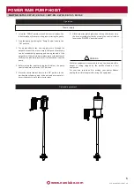
Fig. 6
Grease pail installation
1. Check that the control cabinet lever is in the “NEUTRAL”
position (centre).
2. Slide the 200 kg drum along the base of the inductor. It will
stop up against the inductor limiters. Always use drums that
are compatible with this unit. Do not use damaged drums as
they can cause the inductor plate to get stuck in the drum.
3. Unscrew the bleed rod from the inductor plate, keeping it
nearby or using the housing designed to hold it in the
inductor pump brackets.
4. Move the control cabinet lever to the “DOWN” position.
5. Let the inductor plate descend through the drum. When the
air stops and the grease starts to flow through the bleed
hole, stop the inductor by moving the control cabinet lever
to the “NEUTRAL” position (centre).
6. Insert the rod and tighten it correctly.
7. The unit is now ready to work with. The pump should
already be operative.


