


www.eurolube.com
EUROLUBE EQUIPMENT AB
–
PART NO 26700, 257-51, 257-52 / ART.NR. 26700, 257-51, 257-52
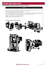
POWER RAM PUMP HOIST
2
www.eurolube.com
2
842 806 R. 09/12
Samoa Industrial, S.A. · Box 103 Alto Pumarín · 33211 Gijón - Asturias Spain · Tel.: +34 985 381 488 · Fax.: + 34 985 384 163
2012_09_26-10:30
Read all instruction manuals, tags, and labels before operating
the equipment.
This equipment is for professional use only.
Do not alter or modify this equipment. Use genuine components
provided from SAMOA Industrial, S.A.
The non compatible fluids may cause damage in the pump and
serious personal injury.
The pump generates high or very high pressures. Do not exceed
the maximum air inlet pressure of 10 bar.
Do not exceed the drum’s pressure limits. Be sure of the drum’s
pressure limitations and regulate the pressure within the safety
limits when supplying air to the inductor plate. Do not try to use
the unit until you have taken all possible precautions to
guarantee that the unit has been installed correctly and that the
base has been firmly secured to the concrete floor.
WARNING
!
Warning and cautions
This symbol aware of serious bodily injury or death if you
ignore the warning described.
!
WARNING
!
CAUTION
This symbol aware of personal injury or property damage if
you ignore the caution described.
Read before use
Avoid electrical discharges. Ensure there are no electrical cables,
devices or accessories above the hoist. Examine the work area
and take the measures necessary to ensure that enough space is
maintained for the installation of the hoist and for the pump to
be lifted as much as possible and that they work correctly.
Maintain a minimum safety distance when raising and lowering
the inductor. Do not get too close; operate it from a safe place,
so you cannot get trapped between the unit and its mobile
elements. Take care when inserting the inductor plate into the
drum.
When not in use, be sure to shut off the air supply to avoid
accidents.
Check that all the operators that work with this unit have been
trained in safe working practices, that they understand their
limitations and use safety equipment when required.
If the unit is not installed correctly this can result in
serious injury or material damage. Read the warnings.
(See warnings and precautions)
.
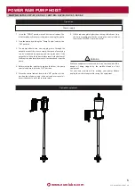
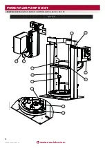
This unit comes completely assembled, apart from the following
details for proper installation and commissioning.
The unit is supplied with the control cabinet in the transport
position. To place the control panel in the working position,
simply disconnect pipes A and B from the control panel (see Fig.
5) and remove the pin from the hole locking the control panel
(see upper arrows) and lower the control panel into its new
working position (see arrow for rotational direction). Once the
control panel is in place, insert the pin making sure the holes of
the new position coincide. This will lock it in the working
position. Then connect the pipes in the lower part of the control
panel according to the diagram (see Fig. 5).
Installation
To facilitate its handling, the unit is supplied with a pallet system
integrated in the design. This system is composed of two
galvanised sheet metal profiles bolted to the base plate. Once
you have selected where you will secure the unit, it is necessary
to remove these profiles; to do this, loosen and remove the
screws that secure them and then remove the profiles in the
direction of the arrows. Take care when doing so to avoid
possible accidents.
Once the definitive location of the unit has been defined, pay
special attention to the work area that will be above the
inductor; this work area shall be free of objects and any electrical
devices. Once you have finished the above step, secure the unit
definitively. To do this, firmly secure the base to the concrete
floor using anchor bolts (not included in the supply). The base
plate itself can be used as a pattern to establish the correct fixing
locations.
!
WARNING


