background image

5

output from converter

Transmitted Data – wire B

6

not used

7

GND

Shield - ground

8

GND

Shield - ground

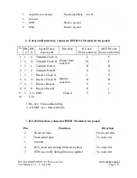
2. Eurocom B interface, connector DSUB-9/15 female (front panel)

No

DB

9

DB

15

Signal Name 

Eurocom B

Direction

RL-xxx 

TDM connector

AN/GRC-xxx

Eurocom In/Out

1

1

4 Transmit Clock A

Output from 
converter

L

F

2

6

12 Transmit Clock B

M

E

3

2

1 Transmit Data A

H

H

4

7

9 Transmit Data B

G

G

5

3

7 Receive Clock A

Input to 
converter

J

S

6

8

15 Receive Clock B

K

R

7

4

3 Receive Data A

F

T

8

9

11 Receive Data B

E

J

9,

10

5

2,6

8,14

GND

Chassis

V

V

 1. RL-xxx : Ericsson/Konsberg
 2. AN/GRC-xxx : Marconi/Ultra

3.

RS-232 interface, connector DSUB-9 female (rear panel)


Pin

Function

Direction

2

 Received data

From converter

3

Transmitted data

To converter

5

 Ground

4

 RTS (used only during firmware update)

To converter

7

 DTR (used only during firmware update)

To converter

TEL-KA EUROCOM B / E1 Mux converter 

www.tel-ka.com.p

l

User Manual v.3.1   4. Apr. 2014

Page 5/13

Summary of Contents for E1 mux

Page 1: ...Zak ad Produkcyjny TEL KA EUROCOM E1 mux converter box User Manual Warszawa 2010 14 TEL KA EUROCOM B E1 Mux converter www tel ka com pl User Manual v 3 1 4 Apr 2014 Page 1 13...

Page 2: ...TEL KA EUROCOM B E1 Mux converter www tel ka com pl User Manual v 3 1 4 Apr 2014 Page 2 13...

Page 3: ...ers ITU G 703 chapter 9 RJ 45 socket 1 2 Rx 4 5 Tx 6 7 GND 5 Eurocom interface B type as per EUROCOM D 1 1986 IB6 pages IB6 1 IB6 5 connector D SUB 9 female type 6 RS 232 interface configuration firmw...

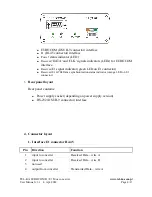
Page 4: ...ator orange LED on E1 connector 3 Rear panel layout Rear panel contains Power supply socket depending on power supply version RS 232 DSUB 9 connector interface 4 Connector layout 1 Interface E1 connec...

Page 5: ...mit Data B G G 5 3 7 Receive Clock A Input to converter J S 6 8 15 Receive Clock B K R 7 4 3 Receive Data A F T 8 9 11 Receive Data B E J 9 10 5 2 6 8 14 GND Chassis V V 1 RL xxx Ericsson Konsberg 2 A...

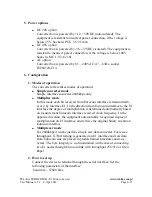
Page 6: ...rocom interface to the E1 interface the degree of multiplication is determined automatically based on measurement Eurocom interface received clock frequency In the opposite direction the equipment aut...

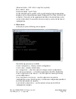
Page 7: ...ns are available Check configuration display current configuration Check status display current status Set configuration select this option to change current configuration Set common parameters set co...

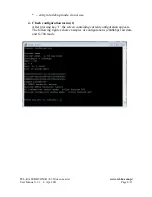
Page 8: ...enu 1 After pressing key 1 the screen containing current configuration appears The following figures show examples of configurations 2048kbps raw data and G 704 mode TEL KA EUROCOM B E1 Mux converter...

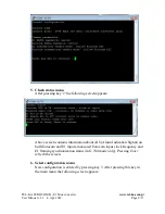
Page 9: ...measured Eurocom input clock frequency and E1 framing synchronization status in G 704 mode only Pressing Enter refresh the screen 6 Select configuration menu New configuration is entered by pressing...

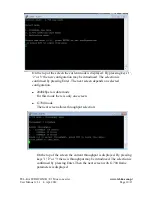
Page 10: ...data mode For this mode there is only one screen G 704 mode The next screen allows throughput selection On the top of the screen the current throughput is displayed By pressing keys 1 2 or 3 the new...

Page 11: ...s selected The current occupied slots map is displayed on the top occupied slots are marked by X By pressing key 1 and next the Enter the default map is selected Pressing key 2 allows arbitrary slot o...

Page 12: ...enable mode Last parameters are important only in certain modes 8 Load configuration from memory menu This option allows loading the previously saved configuration from the non volatile memory 9 Save...

Page 13: ...emoval 1 Plug off power supply cable 2 Unscrew four screws holding rear panel 3 Unscrew four screws holding front panel 4 Disconnect flat cable from board 5 Pull out converter board in rear panel dire...

Reviews: