


Disassembly
2 - 12 Removing and Installing the Processor
2.Disassembly
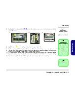
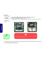
5.
Turn the release latch
towards the unlock symbol
, to release the CPU (
Figure 8d
).
6.
Carefully (it may be hot) lift the CPU
up out of the socket (
Figure 8e
).
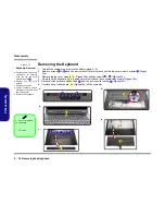
7.
See
page 2 - 13
for information on inserting a new CPU.
8.
When re-inserting the CPU, pay careful attention to the pin alignment, it will fit only one way (DO NOT FORCE IT!).
C
D
Figure 8
Processor Removal
(cont’d)
d. Turn the release latch to
unlock the CPU.
e. Lift the CPU out of the
socket.
C
d.
e.
D
Caution
The heat sink, and CPU area in general, contains parts which are subjected to high temperatures. Allow
the area time to cool before removing these parts.
Unlock
D. CPU
Summary of Contents for B7110 Service
Page 1: ......
Page 2: ......
Page 3: ...Preface I Preface Notebook Computer B7110 Service Manual ...
Page 24: ...Introduction 1 12 1 Introduction ...
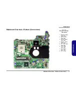
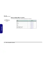
Page 43: ...Part Lists Top A 3 A Part Lists Top Figure A 1 Top 黑色 非耐落 灰色 ...
Page 44: ...Part Lists A 4 Bottom A Part Lists Bottom Figure A 2 Bottom ...
Page 45: ...Part Lists LCD A 5 A Part Lists LCD Figure A 3 LCD 非耐落 ...
Page 46: ...Part Lists A 6 HDD A Part Lists HDD Figure A 4 HDD ...