background image

5 Programming examples

5.1.1 Besondere Steuerfunctionen: 

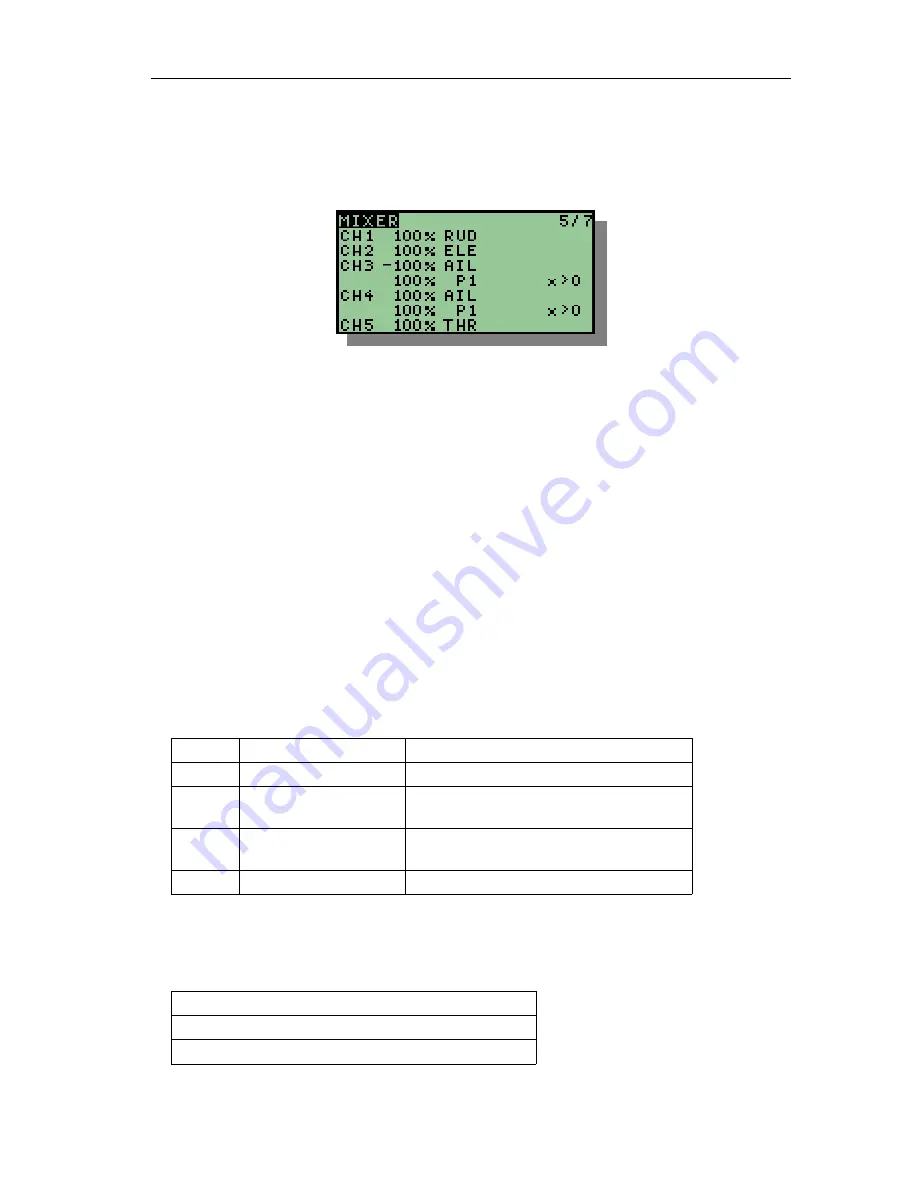
Jedes Querruder mit einem separaten Servo angesteuert, so dass diese mit P1 

als Bremsklappen verwendet werden können.

5.1.2 Erläuterung: 

Die Steuerfunctionen RUDer, ELEvator und THRottle werden 1:1 an die Ausgänge 

1, 2 und 5 übertragen.

P1   (Bremsklappen)   wird   sowohl   auf   Ausgang   (Kanal)   3   wie   auch   4   gemischt. 

Dabei werden aber nur positive Werte berücksichtigt, da ansonsten auch in die ent-
gegengesetzte Richtung gemischt wird.

Die Querruder (Aileron) werden für eine Ruderfläche positiv, für die andere negativ 

gemischt, so dass sich ein entgegengesetzter Ausschlag ergibt. 

Sind   allerdings   die   Servos   spiegelverkehrt   angeschlossen   (was   wohl   der 

Normalfall   Ist)   müssen   die   Querruder   gleichsinnig   und   die   Bremsklappen 
gegensinnig   gemischt werden. Alternativ können auch die Ausgänge (Servo­
kanäle) invertiert werden. 

Kanal 1:  Seitenruder

1:1 Stick Seitenruder

Kanal 2:  Höhenruder

1:1 Stick Höhenruder

Kanal 3:  Querruder links

-100% Stick Querruder
1:1 Landeklappen P1

Kanal 4:  Querruder rechts

1:1 Stick Querruder
1:1 Landeklappen P1

Kanal 5: Motor

1:1 Stick Gas (THROTTLE)

5.2 Segler mit 4 Klappen Flügel

Belegung der Kanäle:

Kanal 1: 

Seitenruder

Kanal 2: 

Höhenruder

Kanal 3: 

Querruder links außen

28

Summary of Contents for Th9x

Page 1: ...Th9x M AN U AL E URG LE TH 9X N G ...

Page 2: ...Author Thomas Husterer Josef Glatthaar Version V1 1 V1 2 Firmware r46 V1 3 Firmware r59 2010 Thomas Husterer ...

Page 3: ...agnosis and calibrating 16 Global Setup I 16 Global Setup II Options 17 Trainer Mode 17 Software Version 18 key diagnosis 18 Diagnosis of Analogue inputs and calibrating of battery voltage measurement 19 Calibrating the sticks 19 Kapitel 4 Function 21 4 1 Power on sequence 21 4 2 Data flow 21 Calibrating 22 Expo 22 Trim 24 Mixer 24 Curves 24 Limits 25 4 3 Trainer mode 25 4 4 Flash programming 25 P...

Page 4: ...ng 28 5 2 Segler mit 4 Klappen Flügel 28 Besondere Steuerfunctionen 29 Erläuterung 29 5 3 Motormodell mit Einziehfahrwerk und Fahrwerksklappen 30 5 4 Hubschrauber mit Pitch 30 5 5 Hubschrauber mit 120 Anlenkung 30 5 6 Flugphasenschalter 30 4 ...

Page 5: ...remote control Eurgle th9x also sold under some other labels like Imax Turborix or Turnigy manufactured by FlySky is a very low cost 2 4GHz radio with impressive hardware features but with a less convincing firmware T 5 ...

Page 6: ...erent values for up and down movement 4 pitch curves with 5 or 9 nodes dynamic memory management servo reverse feature and tunable servo range limits expo and dual rate features tunable battery warning support for display lightening hardware upgrade necessary trainer mode with selectable channel behaviour stick calibration timer with three modes option switches for several features 6 ...

Page 7: ...exit exit current menu and return to the calling menu This is onlyvalid when the cursor is positioned at the top right edge else move the cursor to the top right edge LONG key exit return immediately to the uppermost screen Key can be pressed short or long or very long and each time another action can be triggered Most actions appear immediately after a sort key press When a key is pressed for lon...

Page 8: ...nced by some buzzer beeps 3 2 Main screen Screen contents the current model name NURI a cursor selection either at Th9x or at the model name the battery voltage 6 9V the remaining timer value the output values by numbers or in a grafical representation the trimmer values in a grafical representation key function LONG Open menu set Global Setup LONG Open menu set Model specific Setup LONG Move to m...

Page 9: ... they are cycled by pressing the left or right key The menü 1 7 is used to select one of 16 memory slots which holds any setup data related to one model key function cycle through the model menus 3 3 1 Model selection 1 7 Select one of 16 memory slots by cursor movement up or down Then activate this slot by pressing exit or by cycling to the next model menu Please notice the memory free value in t...

Page 10: ...ition and then change the value In field Proto you can select one of several transmitter protocols Normaly you select PPM here In field Timer you can preset a count down start value and a count down mode This value is then decremented according to the selected modeOFF ABS THR THR OFF no decrementing ABS always count down THR only count down when the Throttle Stick is not in its neutral position TH...

Page 11: ...po function 3 7 In this menu you can set up an exponential behaviour for each of the four sticks Select a value between 100 up to 100 You can open a submenu Expo function Details to see even more settings like a dual Rate switch and a dual rate expo function key function 1 move cursor up and down 2 change vlaues 3a open menü Expo function Details 3b reset cursor to the upper right edge 4a leave th...

Page 12: ...etup trim values 4 7 Here you can swap the trim values to a base value After this operation the trim values in the main screen are repositioned to zero key function 1 move cursor up and down 2a add the trim value to the base value and reset the trim value to zero 2b reset the base value 3 reset cursor to the upper right edge 4a leave this menu 4b cycle to the next menu 12 ...

Page 13: ...e delay values Switches are available in a normal or in an inverted style Curves There are 8 kinds of curves 0 0 x cv1 cv2 cv3 und cv4 no curve bzw y x 0 y x x 0 else y 0 0 y x x 0 else y 0 x y x Cv1 Cv4 Use one of four user defined curves Cv1 and Cv2 have 5 nodes at x 100 50 0 50 100 Cv3 and Cv4 have 9 nodes at x 100 75 50 25 0 25 50 75 100 key function 1 move cursor at or between two lines 2a ch...

Page 14: ... switch selects one of two fixed values as input values and the line is calculated with the whoe set of parameters When SRC MAX or FUL then the switch can switch on the whole line or it can switch off the whole line In the last case no one of the remaining parameter has any effect SPEED These two values determine the speed in which rising or falling input values are propagated to the output channe...

Page 15: ... key function 1 move cursor up down 3 change value select predefined curve Tjhis is only valid if cursor is at PRESET 4 leave menu 3 3 10 Limits 7 7 In this menu you can revert output channels and you set up the output value limits 15 ...

Page 16: ...group of menus is combined any setups that are not model specific The menus are numbered as well and can be cycled with the left and right keys as the group above key function Cycle through the menus This is only valid if the cursor is positioned at the upper right edge 3 4 1 Global Setup I In this menu you can change some global values Screeen contents The contrast value The warning level for the...

Page 17: ...nus where input values are selected key function 1 move cursor up down 2 change values 3 reset cursor to the upper right edge 4a leave this menu 4b cycle to the next menu 3 4 2 Global Setup II Options In this menu you can select several options like warnings or the key beep 3 4 3 Trainer Mode Here you can decide how each Input stick is handled in trainer mode Each line shows RUD the input channel ...

Page 18: ... the students radio this channel has to be connected to one single stick RUD Here you can define a switch which controls this trainer line Cal This line shows the input values which are received from the stu dents radio If you press Menu then the current values are defined as reference values for the student inputs 3 4 4 Software Version Shows the current software version key function 1a leave thi...

Page 19: ... surement Shows the values of all analogue inputs with 10 bit resolution The stick values are also shown in Value number eight shows the battery voltage Here you can also calibrate the shown voltage level key function 1 move cursor up and down 2 change shown battery voltage 3 reset cursor to the upper right edge 4a leave this menu 4b cycle to the next menu 3 4 7 Calibrating the sticks 19 ...

Page 20: ...ursor down while holding the sticks key function 1 move cursor to SetMid move all sticks into the center position and hold them 2 move cursor to SetLow move all sticks to the lower left edge and hold them 3 move cursor to SetHigh move all sticks to the upper right edge and hold them 4 move cursor to Ready now its finished 5 change to previous menu and check the shown persentage values 20 ...

Page 21: ... stick is located at its initial position In case of fault a warning is given Then any switches are checked If at least one switch is not in its off position then we are led to the switches dialog which shows us any swith value Each warning screen can be left with te exit key 4 2 Data flow ow we mentioned earlier this radio works with a very simple calculation model Any stick value and any switch ...

Page 22: ...e handled according to this 4 2 2 Expo The expo function transfers the linear input values into some output values with non linear behaviour This means that the sensibility of a stick is dependent from the wor king position of this stick As an approximation to the expo function the following polynom is used y f x x 3 k x k 1 with 0 k 1 22 Kalibrierung Expo Trimm RUD THR ELE AIL P1 P2 P3 Switches M...

Page 23: ...e sensitivity of the stick at several working positions The polynom was used in the implementation because we can evaluate it without usage of any floating point arithmetics define RESX 512ul define RESK 100ul uint16_t expou uint16_t x uint16_t k k x x x 1 k x return unsigned long x x x 0x10000 k RESX RESX 0x10000 RESK k x RESK 2 RESK This implementation needs only one real 32 bit Integer Division...

Page 24: ...resolution in outer ranges At the same time we can reach the whole value range in 31 stepts 4 2 4 Mixer The mixer block combines several input channels to the output channels The inputs are weighted by some persentage value an they are assigned to the outputs Additio nal to this weight we can assign a user defined curve to this value and we can assign some delay values to one mixer line 4 2 5 Curv...

Page 25: ...udents radio must have the powerbutton switched off Power Off is students radio no sender module necessary Power On is trainer radio Both radios become connected with a stereo cable After connecting the radios the students radio gets powerd Now change to the trainer menu and look for the students stick values Any further computations are done in the trainer dvice Student and trainer values can be ...

Page 26: ...twendig die Fuses in irgend einer Weise zu ändern Falls dies doch einmal passiert habe ich hier meine Originalwerte aufge listet sig 1e 96 02 ff Atmel AVR ATmega64 Lock Bits 0xff 0b11111111 Fuses low 0x0e 0b00001110 Fuses high 0x89 0b10001001 Fuses ext 0xff 0b11111111 26 ...

Page 27: ...erden Es gibt also keine spezielle Zuordnung wie dies bei anderen Computersendern zum Teil der Fall ist Sinnvoll ist es aber trotzdem die Ausgänge zu Beginn der Program mierung festzulegen und so zu belassen Bei den Eingängen Steuerknüppel Schalter Poti gibt es eine einzige Zuordnung Diese betrifft den Timer Wird diese function genutzt muss zwingend der richtige Mode gewählt werden Außerdem sind d...

Page 28: ... Ruderfläche positiv für die andere negativ gemischt so dass sich ein entgegengesetzter Ausschlag ergibt Sind allerdings die Servos spiegelverkehrt angeschlossen was wohl der Normalfall Ist müssen die Querruder gleichsinnig und die Bremsklappen gegensinnig gemischt werden Alternativ können auch die Ausgänge Servo kanäle invertiert werden Kanal 1 Seitenruder 1 1 Stick Seitenruder Kanal 2 Höhenruder...

Page 29: ...ittelpositionen gestellt werden Schnellflug Thermikflug Beim Setzen der Landeklappen soll das Höhenruder verzögert korrigiert werden Beim Landen soll die Butterfly Stellung verwendet werden bei der die Querru der nach oben und die inneren Klappen nach unten ausschlagen 5 2 2 Erläuterung Butterfly Stellung wird über den Schalter THR aktiviert Die Flugphasen werden mit Schalter RUD aktiviert und mit...

Page 30: ... 10 P1 für Flugphasen aktiviert über RUD Kanal 5 Querruder rechts außen 1 1 Stick Querruder 50 Butterfly invertiert 10 P1 für Flugphasen aktiviert über RUD Kanal 6 Klappen rechts innen Bei Betätigung des Schalters THR werden die Klappen LONGsam ausgefahren 10 Querruder werden dazugemischt 10 P1 für Flugphasen aktiviert über RUD 5 3 Motormodell mit Einziehfahrwerk und Fahrwerksklappen tbd 5 4 Hubsc...

Page 31: ...31 ...
Reviews: