


Euphonix System 5 Installation Guide
System 5 Components
43
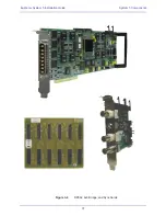
SC264 System Computer
Figure 3-8
SC264 Front and Rear Panels
VGA Connector
(DA-15): Main video monitor connection.
Keyboard
(PS/2): Main keyboard connection.
Mouse
(PS/2): Main trackball connection.
Serial Port 1
(DE-9): Com1; currently not used. (Com2 is wired internally to the
LAN Port 1
(Onboard RJ45): Connect to EuCon Network Switch (provided).
LAN Port 2
(Auxilary RJ45): Optional connection for external network. Replaces the
Serial Port 2
(DE-9, top) and
Serial Port 3
(DE-9, bottom): Com3 and Com4, res-
pectively; currently not used
USB Ports:
Connect a USB memory device to one of these ports for file backup, appli-
cation installations or updates. Connect the Ontrack ADU-200 KVM switch to enable
switching between integrated DAW displays (see page 41).
SNMP board’s Com port.)
TT002
(75-ohm BNC, DE-9 female, DE-9 male): BNC port is for Bi/Tri-Level Video
input; DE-9 female is for RS422 (Sony 9-pin); DE-9 male is for Midi Machine Control
and Time Code I/O (via breakout cable).
GPIO Port 1
(DC-37): GP Inputs and Outputs 1 to 16.
GPIO Port 2
(DC-37): GP Inputs and Outputs 17 to 32.
11
Hybrid Pilot used for DAW integration.
11
12
13
14
Power Connectors
(IEC): Accepts two standard IEC power cords (provided). Two auto-
ranging switching supplies accept voltages between 100–240 VAC, 50–60 Hz.
12


